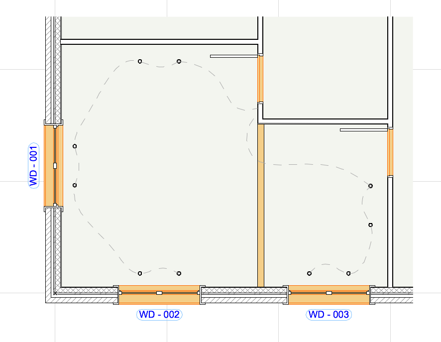
With a single click, create a 3D Document based on the Floor Plan: a section view, based on a horizontal cut plane in the Floor Plan window. Define the projection by setting a cut plane height and the projection direction either upwards (toward the ceiling) or downwards (to the floor). This type of 3D Document shows the cut part of the model, including sections of vertical structures (e.g. walls, openings). Interface and settings are based on the 3D Document.
This is useful, for example, to display the load-bearing structures on a slab plan, or as a reflected ceiling plan. Use it also to create shaded Floor Plan views for presentation/interior design.
•Create 3D Floor Plan using single command
•Filter content by Marquee, cutting planes, and element type
•Save document as view; print or place on Layout
•Dimension 2D elements on ceiling plan
•Show hidden lines
•Option for Reflected ceiling-type view
•Model-based element display (including Solid Element Operations)
•Options for display include cut and uncut attributes, contours, true 3D vectorial hatching, shading, shadow and sun effects