You may prefer the editing plane in a different location than the default. You can change the editing plane either before you begin input, or during input. The available commands vary depending on your editing situation.
Note: The Offset and Snap to Story commands are available only before you begin input.
Where To Find Editing Plane Commands
To reposition the editing plane, use the commands from one of the following places:
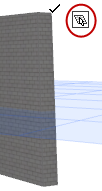
•Click the square-shaped editing plane “Grip”.
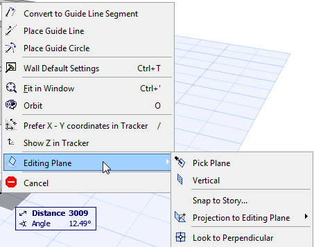
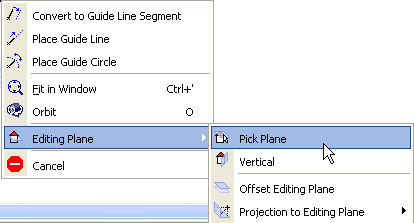
•Right-click to bring up a Context menu, then choose Editing Plane.
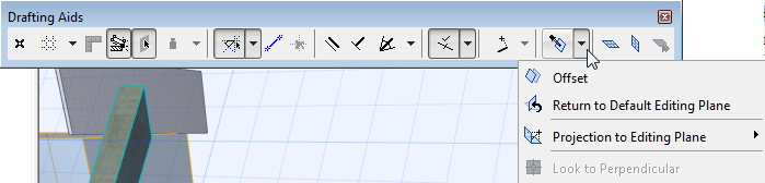
•Access the commands from the Drafting Aids Toolbar.
•Access the commands from View > Grid and Editing Plane Options.
Use this command prior to element input.
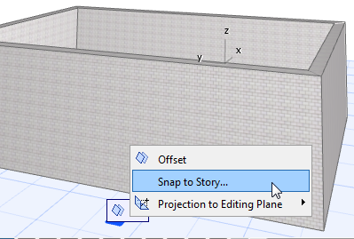
To snap the editing plane to a specific level corresponding to a project story:
1.Bring up the Editing Plane commands.
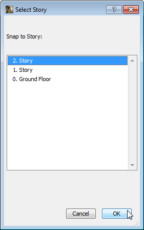
3.From the appearing dialog box, choose the project story to which you want to move the editing plane.
You may wish to move the editing plane by offsetting it - for example, if you need to create intersection points between existing elements and the editing plane, at a different location than the current editing plane.
Use this command prior to element input.
To offset the editing plane:
1.Bring up the Editing Plane commands.
2.Choose Offset.
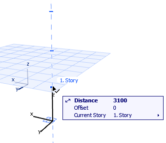
3.Use the cursor to drag the editing plane to the desired position, or define the offset distance numerically. Notice that a Guide Line appears marking the story positions, to make it easier to place the editing plane.
Offset Editing Plane Example
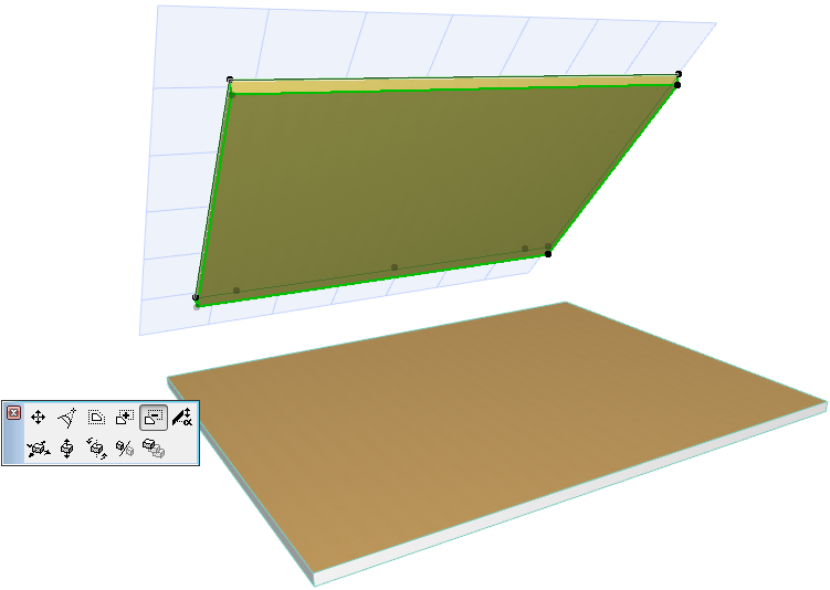
For example, you wish to edit the Slab shown below by dragging its cornerpoint to a new position. You want to drag it so that the Slab corner will be vertically aligned to the Wall above it, at the place where the Wall is one meter high.
The solution is to offset the editing plane (currently the same plane as the top of the slab) by 1 meter and find the place where the plane intersects the Wall.
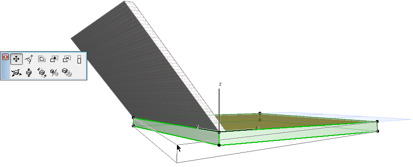
1.From the Editing Plane grip or context menu, choose Offset.
2.Start moving your cursor upwards, and enter the one-meter distance into the Tracker.
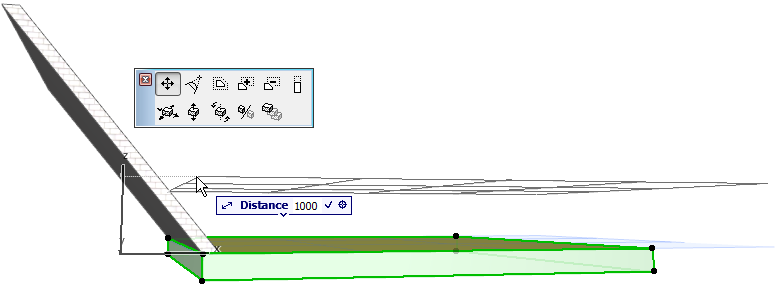
3.The editing plane jumps to the required position.
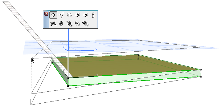
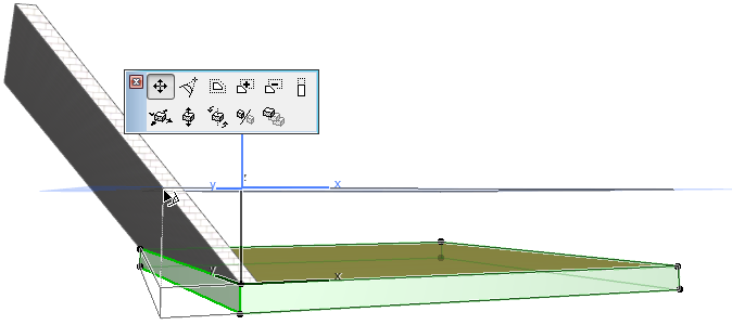
4.While dragging the Slab cornerpoint, find the intersection of the Wall with the editing plane at its new location. Click to place the Slab point.
Other Editing Plane Commands
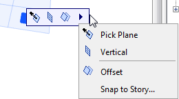
Choose one of the options for your preferred editing plane orientation (the available options vary depending on the orientation of the current editing plane).
•Next Plane: Click this to switch to the next editing plane that makes sense in the editing context.
•Pick Plane.
See Pick Plane.
•Horizontal: Rotates the editing plane to a horizontal position.
•Vertical: Rotates the editing plane to a vertical position.
See Offset Editing Plane.
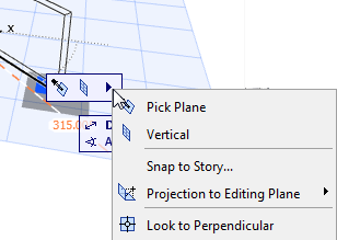
•Look to Perpendicular: Sets up the 3D window so that it is perpendicular to the Editing Plane.
See Projection onto Editing Plane.
See Lock to Plane.
Once you click this command, the grey rectangle “plane chooser” feedback appears.
Do one of the following to pick the desired plane for the editing plane:
•Move the cursor onto any plane of an existing element. A rectangle will help you see the plane.
•Click on any three points in space (such as three element hotspots) to define a plane.
•Click on an element edge plus another point (in either order) to define a plane.
Pick Plane Example
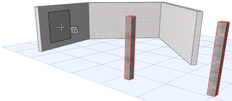
For example, say you need to cut a hole in slanted roof plane. The hole in the Roof must be a projection of a 2x2 meter square as measured on a horizontal plane.
When you select the Roof and the Subtract from Polygon command, the editing plane automatically corresponds to the Roof plane.
Here, however, the horizontal plane at the story level would a more useful editing plane, because that is where you want to measure the hole dimensions.
1.From the context menu, choose Editing Plane, then Pick Plane. (Or access this command from the editing plane grip.)
2.Move your cursor until the grey rectangle “plane chooser” icon indicates the plane atop the slab. Click to pick that plane as the editing plane.
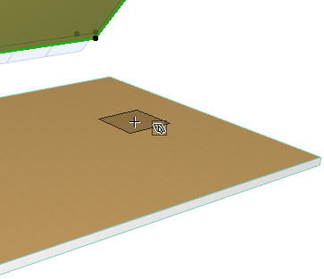
3.Continue the editing operation by defining the shape of the hole numerically on the Floor Plan. Note that your editing is projected onto the Roof.
By default, as you perform graphical editing, your cursor is moving on the editing plane. If needed, you can redefine the direction of this cursor projection.
To change the cursor projection with respect to the editing plane:
1.Begin the editing operation.
2.From the context menu, select Editing Plane Projection.
Alternatively, click on the Editing Plane Grip to bring up the same commands.
3.Choose one of the projection options:
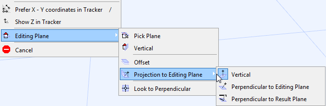
•Vertical
•Horizontal
•Perpendicular to Editing Plane
•Perpendicular to Result Plane
Use this command lock input to the existing editing plane before you start creating the new element.
This is useful, for example, if you wish to create an element on the existing editing plane, by tracing the shape of an existing element (e.g. roof) on another plane.
1.Bring up the Editing Plane commands.
2.From the Projection to Editing Plane sub-menu, choose the Lock to Plane toggle.
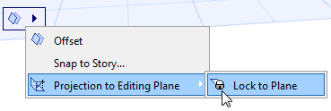
The new element will be placed onto the editing plane, even if your cursor is on another plane.
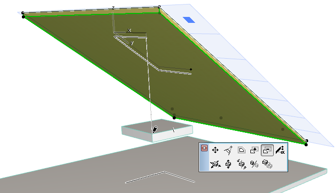
Editing Plane Projection Example
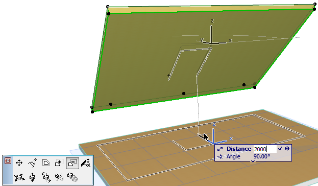
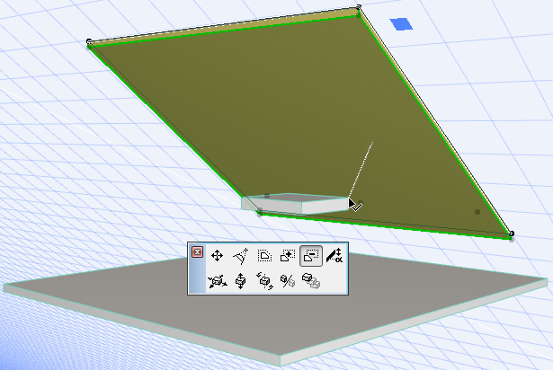
For example, here you want to cut a hole in the Roof so the hole is vertically above the four points of the Slab.
1.Select the Roof and choose Subtract from Polygon from the pet palette.
2.Click on a corner of the Slab.
3.Notice that the projection line is perpendicular to the editing plane, which is not what you need.
4.Change the projection to Vertical:
•From the context menu, select Editing Plane Projection.
Alternatively, click on the blue “Editing Plane Grip” to bring up the same commands.
•Choose Vertical.
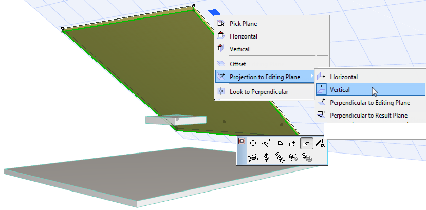
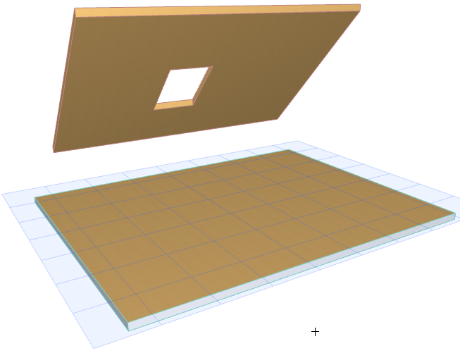
5.The editing is now projected vertically toward the editing plane.
6.Draw the hole in the Roof as desired, by clicking on the four corners of the slab to project its geometry vertically onto the Roof above.