
Aligning Elements to a Surface in 3D
The Align to Surface relative construction method is only active when working in the 3D Window. It enables you to fit elements onto non-horizontal planes when working in 3D views.
This method automatically identifies the intersection of a selected plane and the working plane of the cursor. The working plane is often horizontal. However, in special cases, for example when moving a hole in a roof plane, the cursor’s working plane is angled. It is also possible to align to curved surfaces, for example when fitting an object to a curved wall. The limitation here is that if the cursor is moving in an angled plane, it is not possible to fit to a curved surface, only the tangential plane of the surface.
Using the Constraint when Creating New Elements
1.To use the constraint, first open the 3D Window.
2.Choose the tool for the element you wish to add.
3.Adjust your User Origin if necessary.
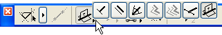
4.Choose and activate the Align to Surface Relative Construction method in the Control Box.
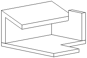
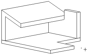
5.Click on any surface in the 3D view you want to align your new element to.
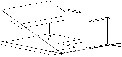
6.A black dot will appear on the selected plane at the height of the current User Origin. The dot will follow the cursor constrained to the intersection line of your reference plane and the User Origin plane.
7.Click where you want to start drawing your new element. The element will be constrained to the intersection line. Finish drawing the element in the usual way.
Using Align to Surface with Existing Elements
1.Activate the 3D Window.
2.Adjust the User Origin if necessary.
For more information, see Origins.
3.Select the element you wish to edit.
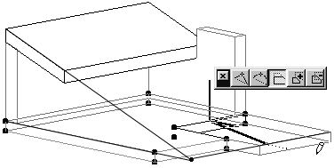
4.Choose the Edit command you wish to execute, e.g., stretch an edge of a slab to the intersection of a roof and the User Origin.
5.Click a reference point or edge to start editing.
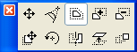
6.Select the Align to Surface icon from the Drafting Aids toolbar or the Control box, and activate the constraint as described above.
7.Choose your reference plane.
8.Finish editing the element.