See also Rotating Beam and Column Profiles, below.
To rotate an element:
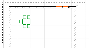
•Select the Element.
•Select the Edit > Move > Rotate command (or Move > Rotate from the selected element’s context menu). Alternatively, click again on a node or edge of the selected element to bring up the pet palette, then choose the Rotate command.

Or use the Ctrl (Cmd) + E shortcut.
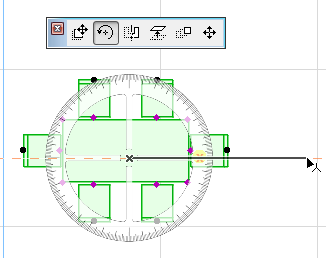
•Click to define the center of rotation of the selected elements.
•Click to define the starting point of the rotation arc and its radius.
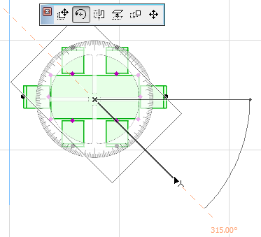
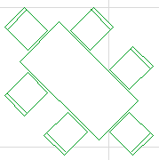
•Move the cursor and click to complete the rotation arc.
Note: To Rotate a Copy, press Ctrl while executing the regular Rotate command.
You can rotate selected elements in the Floor Plan or in the 3D Window, and drawing elements only in Section/Elevation/IE, 3D Document, and Detail/Worksheet windows. Even in the 3D Window, rotation is always performed across a horizontal plane.
Rotating Beam and Column Profiles
There are two ways to rotate Beams and Columns with respect to their profiles.
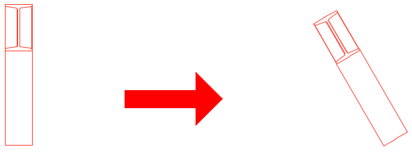
The regular Rotate command (described above) rotates the Beam/Column element together with its extrusion vector (i.e. the Beam reference line or the Column axis.)
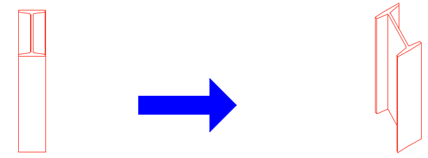
When using a Beam or Column that is a complex profile, you may wish to rotate the profile itself.
To do this, use the Rotate Profile command from the pet palette of the selected element in the 3D window.
Note: The same command is available as Rotation Angle or Rotate Profile in the Settings dialog boxes of the Column/Beam elements.)
Rotating Shell Profiles
Shell profiles can also be rotated graphically, using the Rotate Profile command from the pet palette of selected Shells.