Examples of Floor Plan Display Settings
Suppose your settings are as follows:
•Show on Story: Automatic
This means that each multi-story construction element will be displayed on each relevant story of the Floor Plan.
•Floor Plan Display: Projected with Overhead
This means that each construction element will be displayed in its entirety, its cut portion, its overhead portion, and its uncut portion, with the line types and pen colors you set in the dialog box for each of these parameters
•Show Projection: Entire Element
This means that the displayed projection is not limited by either an absolute display limit or by a defined vertical range.
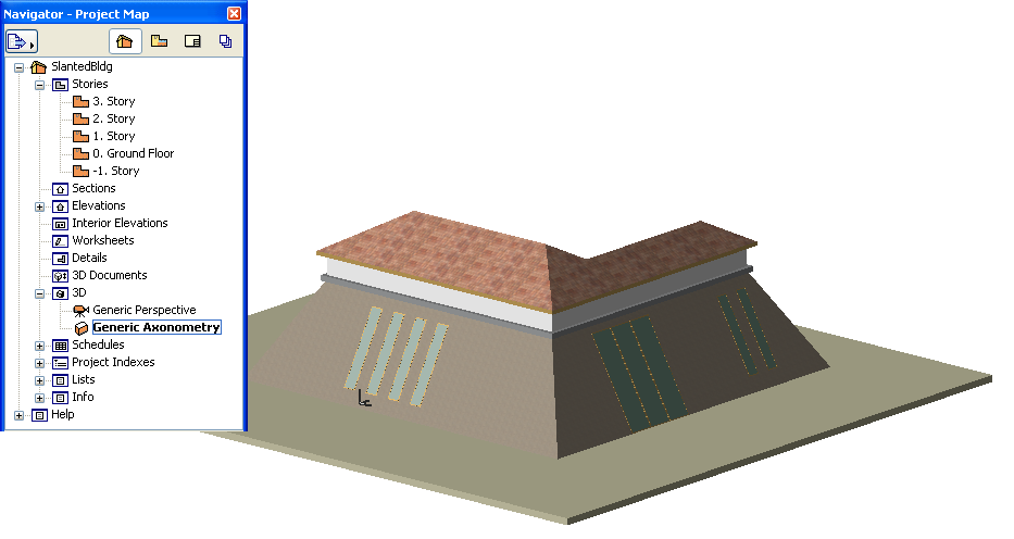
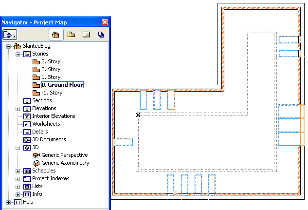
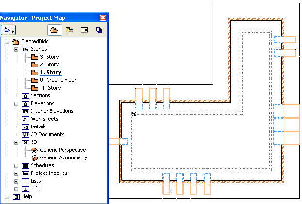
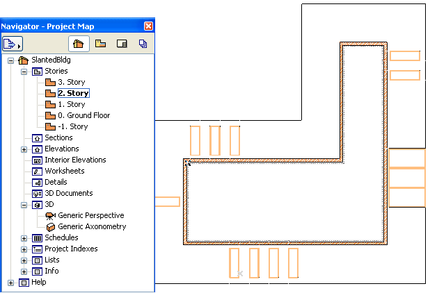
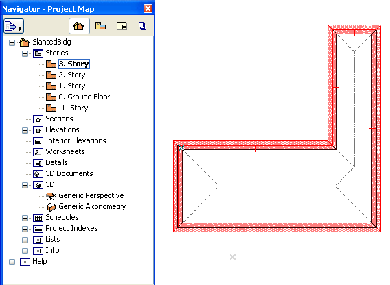
Consider the following building with slanted walls:
As you view the building on its various stories, its Floor Plan appearance changes accordingly: although the entire wall is indicated on every story, the cut and overhead segments are different on every story.
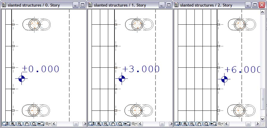
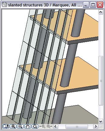
Non-Standard Projections for Construction Elements
In the example below, the structure is shown on 3 stories:
•the Curtain Wall is set to “Projected with Overhead” and “Entire Element”
•the mullions - made of columns - are “Cut Only”
•the round structural columns are set to “Projected with Overhead” and “Floor Plan Range” (on each story, only their relevant section is displayed)