Note: This process is identical for Elevations, Details and Worksheets.
Linked section markers have no model source and do not generate a new viewpoint. Instead, they are placed in the project, then linked by the user to an existing viewpoint, view or drawing whose information is displayed in the marker.
You can place a linked Section marker in any of the following windows: Floor Plan; Section; Elevation; Interior Elevation; 3D Document; Worksheet; Detail.
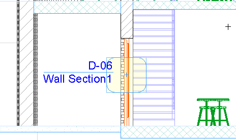
For example, you might create a Wall Section that functions like a Detail:
First, place a source Detail marker in the Section window;
then place a linked Wall Section marker on the Floor Plan which is linked to this Detail.
This linked Section marker points you to the Detail of this wall’s Section.
To place a linked section marker:
1.Activate the Section tool.
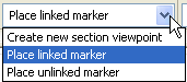
2.In the Info Box or Section Default Settings, make sure that “Place Linked Marker” is selected.
3.Define the Marker Reference using the appearing dialog box.
See Define Marker Reference for Linked Marker.
4.Choose an input method (either Straight Line or Staggered Line) from the Info Box and draw a Section line on the plan.
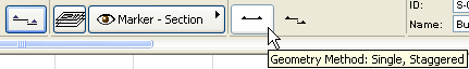
•Straight line: click twice to define each end of the line.
•Staggered line: click as many times as needed to define each segment of the Section line. Double-click to complete the input line.
Note: The Staggered line option is not available for Elevations.
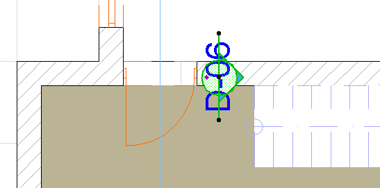
The Eyeball cursor appears.
5.With the eyeball cursor, click on either side of the line to set the orientation of the linked Section marker.
6.The Marker is automatically placed after the section line is completed.