For general information, see The Grid Tool.
This dialog box is available from the Design > Grid System command.
Grid System General Settings Panel

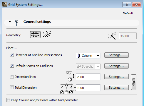
Geometry: Select between orthogonal and curved grid systems. If you select a curved system, then enter a value for the radius of the outermost gridline.
Place...: Check any of the next four checkboxes to place additional elements at each gridline intersection:
•Elements at Grid line intersections: Check this to place elements at grid line intersections. Click the pop-up to select the element type (Column or Object) and click the Settings button to open that element’s settings dialog on top of this dialog.
•Default Beams on Grid lines: Check this to place a Beam element along the grid lines. Click the Settings button to open the Beam settings dialog on top of this dialog.
Note: If you are placing a curved grid system, you have the option to place either straight or curved beams along the gridlines.
•Dimension lines: Check this to place a dimension line between each and every grid line. Enter a value for the offset between the dimension line and the first crossing grid line. Click the Settings button to open the Dimension settings dialog on top of this dialog.
•Total Dimension: Check this to place a dimension line between the two side grid lines. Enter a value for the offset between the dimension line and the first crossing grid line. Click the Settings button to open the Dimension settings dialog on top of this dialog.
Click the chain icon to have identical attributes for dimension lines and the total dimension.
Keep Column and/or Beam within Grid perimeter: Check this to shift the columns and the beams so that will appear inside the perimeter of the Grid system.
Grid System Grid Elements Panel

Grid Element Settings: Click this button to open the Grid Element to set properties for every Grid element in this Grid System. (All Grid elements will look the same.)
Extension: Enter a value for the distance that the Grid line extends beyond the last crossing Grid line
Anchor: Click one of the four positioning buttons to define an anchor by which to place the Grid System.
Markers: Check any or all of the four sides of the Grid System to place Markers. (If you define a rotation during Grid System placement, then these sides will be rotated as well.)
Auto-stagger Grid Markers if they overlap: Check this to automatically stagger Grid markers sideways to avoid overlapping, if the markers would otherwise overlap.
Grid System Naming Rules Panel

Use this panel to define the logic by which to name the Grid lines of this Grid System. You can define separate naming styles for the two grid directions.
•For a curved grid system: circular Grid lines and radial Grid lines.
Note that assigning naming rules to “horizontal” and “vertical” gridlines, as well as the “up” and “down” definitions, are relative to the Grid System’s orthogonal position (if you rotate the Grid System when placing it, the assigned names will be rotated accordingly.)
Custom: Select this to enter names manually for any grid element, using the fields in the Grid Positions Panel: if you click Custom in the Naming Rules Panel, then the Grid line names become editable in the Grid Positions Panel.

Generate names automatically: Select this to auto-generate names for the Grid lines in this Grid System.
Ascending direction: Select one of the two directions (click the up or down arrow) to define in which direction the automatically generated names should be assigned.
•Start at: This field shows the starting value of the Grid element naming.
•Prefix: a static text displayed in front of each auto generated name.
•Suffix: a static text displayed following each auto generated text.
•Style: Choose a style for the auto generated Grid element names: either numbers (1,2,3,...), letters (A,B,C,... or a,b,c,...), or Roman numbers (I,II,III,IV,...)
Grid System Grid Positions Panel
Use this panel to define the number and position of horizontal and vertical Grid lines for this Grid System.
(For a curved grid system: circular Grid lines and radial Grid lines.)

Note that “horizontal” and “vertical” gridlines parameters are relative to the Grid System’s orthogonal position, and rotate along with the Grid.
Add a Grid line: Click the Plus sign to add a Grid line.
Remove a Grid line: Click the Minus sign to remove a Grid line.
Set distance: Click the distance field of any of the listed Grid lines to define its distance from the previous Grid line. The Distance of the first Grid line in the list is always zero.
Distribute: If you do not know the distance you will need between your Grid lines, check the Distribute box for either or both Grid line directions. This will enable you, when you place the Grid system, to set the beginning and endpoints of the Grid system in the given direction, divided into the number of Grid lines defined in the list.