Global Illumination (GI) is a sophisticated method for achieving realistic lighting effects in your model. The algorithm simulates the effects of not just direct light sources, but indirect light effects - that is, inter-reflections caused by light rays bouncing off surfaces.
With CineRender, you can achieve very high-quality renderings using Global Illumination. However, it can greatly increase render time.
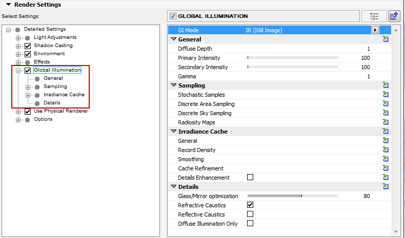
GI Mode: Define the basic GI method for your scene:
•IR (Irradiance Cache) (Still Image): Default method. Typically, you can stick to using IR for still images.
•QMC
•IR/QMC (Still Image)
The advantages of this method are moderate render times combined with a very homogeneous and even dispersion of light.
The Irradiance Cache (IR) method attempts to determine which areas of a scene require more samples and which areas require fewer. The scene setup is analyzed before rendering is begun. During this “prepass”, the scene composition is scanned several times and test calculations are made to determine the optimal number of samples for each region of the image. This allows the number of overall calculations to be optimized and the render times for GI to be reduced, in part dramatically, as compared with the QMC method.
Adjusting the Irradiance Cache calculation
Generally speaking, the predefined values in these additional settings don’t not have to be modified.
Disadvantages of using Irradiance Cache:
Finer details pertaining to light and shadow might be omitted, due to the limited number of shading points. This is where the QMC method has an edge. However, the IR method offers a Details Enhancement option that combines QMC and IR methods in order to compensate for this disadvantage.
See Details Enhancement.
How Does QMC Work?
The QMC method of Global Illumination calculation works under a so-called “brute force” principle. This means that, for each (!) object pixel in the image, a definable number of rays (“Sample Count”) can be “beamed” in a hemispherical pattern into the scene. This is not an adaptive process and the render time will definitely not be reduced.
This bears the advantage that it offers the most precise render results. Small details in shadows and shading can be rendered out that would otherwise not be noticeable if the IR method were used.
The abbreviation QMC stands for Quasi Monte Carlo. This sample mode randomly disperses calculation points throughout the scene. No preferential treatment will be given to, for example, luminous or highly detailed objects. In theory, this sample method offers the most exact results because every point in the image is calculated using the same effort. One disadvantage of using this method is that it increases render times dramatically, which rises linearly as the image resolution is increased. Furthermore, QMC renderings tend to produce unwanted noise, which can only be remedied using very high sample rates. On the other hand this sampling method produces a very realistic dispersion of light.
The QMC sampling method supports all Global Illumination properties, i.e. the application of specific Diffuse Depth, as well as the illumination of the scene using both light sources and materials.
Disadvantages of using QMC:
The render times are maxed out (much longer than with Irradiance Cache) and, since brightness and color values based on a finite and randomly distributed number of rays (“Sample Count”) are ascertained for each pixel, the images will have a slight graininess to them that can only be compensated for by increasing the sample count, which increases render time accordingly. Using Area Lights/GI Portals (indoor scenes, primarily illuminated by light falling through windows) can noticeably improve render quality (which also saves render time).
Of the many GI-related parameters, the Diffuse Depth value can make a significant difference in rendering quality. It defines the number of times light reflects in a scene, i.e. how often a “ray of light” is reflected from surfaces.
•The minimum Diffuse Depth value of 1 (as in the following image) results in only a direct illumination via flat, light-emitting elements. This will be sufficient for most external scenes, with Physical Sky or HDRI Sky providing a significant light source.
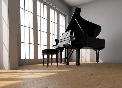
•A Diffuse Depth value of 3 (as in the following image) is required to achieve an indirect illumination, i.e. light reflected from other surfaces. A minimum value of 2 will be required for interior scenes.
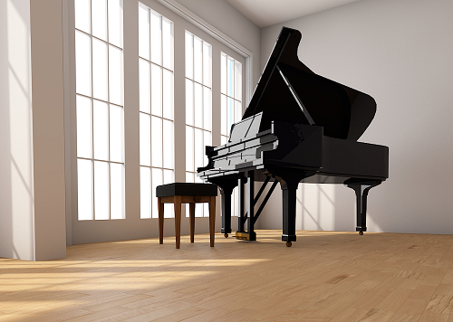
Greater Diffuse Depth values will result in correspondingly, but moderately, longer render times (the difference between a value of 1 and 2 is greater than that between 2 and 8, but the dispersion of light will become increasingly homogeneous, brighter and more realistic. However, the effect at values greater than 3 in a normal scene will become less and less noticeable and the rendered result will simply become brighter.
Note that gamma correction can, within limits, be used to compensate for lower Diffuse Depth values.
Tip: When “real” light sources are used, indirect illumination can already be achieved with a Diffuse Depth value of 1 because the objects illuminated by the light source will be recognized as a luminous object.
Primary Intensity/Secondary Intensity
Use these parameters to adjust the GI brightness based on the number of light reflections. The Primary Intensity parameter affects the regions being illuminated directly; the Secondary Illumination parameter affects reflected light.
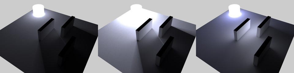
From left to right, the following Primary/Secondary Intensity values:
100%/100%, 300%/100%, 100%/500%
Gamma
This gamma value only affects the indirect GI lighting. Gamma values define how the internally rendered brightness values should be displayed in RGB mode. Simply stated, a progression from the darkest (black) to brightest (white) is defined.
This lets relatively dark renderings (e.g. resulting from a low Diffuse Depth value) be brightened. But be careful - high gamma values will reduce contrast and “flatten” the overall image (values ranging from 1 to 3 have proven to be most effective; in some instances higher values may be necessary). Values less than 1 will darken the image, whereas values greater than 1 will brighten an image.
The Sampling settings here only affect the GI sampling: How many samples should be sent and where in order to gather light from the environment? The first setting - Samples - is the most important; the others are designed for fine-tuning (except for the radiosity maps, if used).
Stochastic Samples
Method: Two methods of defining sample count are used:
•An automatic determination controlled by one of the quality settings (Low, Medium, High, Accuracy)
•A fixed number of samples defined by the Sample Count setting
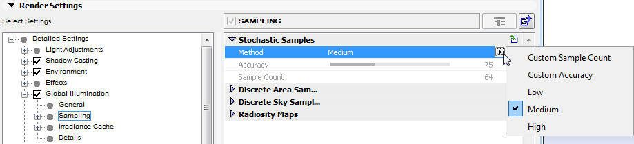
•Selecting Custom Sample Count lets you manually define the Sample Count value
•Selecting Custom Accuracy lets you manually define the Accuracy value
Accuracy: Use this setting to define an optimized sample count. The optimal count depends on the Project (and in IR GI Mode, on the other Irradiance Cache settings as well) and of course the defined Accuracy value.
Sample Count: This setting defines the fixed number of samples to be used. A higher value produces a correspondingly better render quality (for QMC this can be seen in the graininess; for IR the number of spots is reduced).
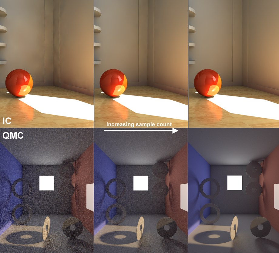
Increasing Sample Count (left to right)
This rendering Sample Count will also be used by the Discrete Area and Discrete Sky Sampling if they do not have a custom count defined (see below).
Discrete Area Sampling
Check Use Area Sampling to enable this method.
In order for this sampling type to work, the GI Area Light option must be enabled in the Surface’s Illumination channel.
See Illumination.
This sampling method sends additional samples to (polygon) Area lights. This will emphasize them disproportionately, which will have a major effect on the quality of the GI.
Note that even if you disable this option, the Area lights will NOT be omitted from the GI calculation. These lights will merely receive no special attention and will be hit randomly by the hemispheric sampling (with a correspondingly grainy result).
Force Per-Pixel: This option is only advantageous in IR GI mode. Normally every light will be taken into consideration for the cache when an Irradiance Cache is created. However, this does not work if you have very small, bright Area lights. The result will be spotty images. If you enable the Force Per-Pixel option, the calculation of the Area lights will be split from the cache and calculated separately (as the QMC GI mode does by default) for each potential pixel (object surfaces but no backgrounds or skies, for example).
Custom Count/Sample Count
Use these fields to define a custom sample count. If Custom Count is disabled, the same number of samples will be used as defined in Stochastic Sampling.
Discrete Sky Sampling
Check Use Sky Sampling to enable this method.
This sampling mode takes into account the sky in particular (e.g., the Physical Sky or a HDRI Sky).
A sky map will be calculated internally during rendering, which will then concentrate the additionally created samples primarily on the brightest regions during rendering. This means that HDRI textures with enough contrast can cast shadows with locally very bright regions.
If this option is disabled, the sky will NOT be omitted from the GI calculation. The sky will merely receive no special attention and will be hit randomly by the hemispherical sampling (the extremely bright sun will produce a grainy image).
Force Per-Pixel: A Sky object with an HDRI texture applied to it is located behind the window.
This option only bears advantages for the IR GI mode. When an Irradiance Cache is created, the sky will normally be sampled and taken into consideration for the cache. For bright regions (sun) or those with smaller surfaces, this method has limits and will result in spotty renderings.
If you enable Force Per-Pixel, the calculation of the light emitted by the sky will be split from the cache and calculated separately for each pixel that comes into question (object surfaces but no backgrounds, skies, etc.), which is how the QMC GI mode works by default.
Custom Count/Sample Count
Use these fields to define a custom sample count. If Custom Count is disabled, the same number of samples will be used as defined in Stochastic Sampling.
Check Use Radiosity Maps to enable this method.
Radiosity Maps are an optional method of GI calculation which makes it possible to create precise QMC renderings with reduced render times (but rendering can also be made faster in IR mode).
Simply put, illumination (light sources, Area lights, sky) on polygons is calculated internally as special textures (Radiosity Maps) during rendering, prior to the actual GI calculation. These Radiosity Maps are then used during the actual GI calculation for faster rendering. This method has several advantages and disadvantages:
Advantages:
•GI calculation is faster
•Radiosity Maps can be saved and re-used.
Disadvantages:
•The actual diffuse depth (number of diffused light reflections) is 1 (2 in the case of Area lights and/or skies), which darkens the rendering. To some degree, this can be offset by increasing the Gamma value.
•More memory is required
•Special objects such as perfect spheres are not supported.
•When using simplified geometry (e.g., single-polygon walls without thickness), light can seep through. This can be prevented by modeling more realistically, i.e., giving walls a thickness.
Tips:
•Radiosity Maps can be made visible (set the Mode control to “Shading”).
•Radiosity Maps should have a light dispersion that is as homogeneous as possible.
Map Density: Use this setting to define the Radiosity Map resolution. The higher the value, the smaller the Texels will be (the small squares for which a uniform color/brightness is ascertained) and the higher the quality of the Radiosity Map will be (with correspondingly longer render times and increased memory requirements).
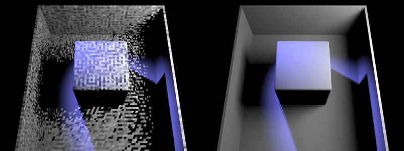
At left a Radiosity Map of poor quality, at right of better quality
You can make Texels visible without complicated calculations by setting the Mode to Texels and rendering the Project.
If the Texels are too large and light seeps through, reducing the size of the Texels can help alleviate this problem.
Sampling Subdivision: This setting can be understood as a type of antialiasing for Texels. A value of 2 will divide a square Texel into quarters and a color will be calculated for each quarter and averaged for that Texel. A value of 3 will divide the Texel into 9 equal parts and so on. Higher values will result in better quality and correspondingly longer render times and greater memory usage.
Mode
•Normal: This is the normal render mode in which no Texels will be shown. This mode should be used for final renderings.
•Shading: This mode is the most comprehensive because it simultaneously shows the Texel dispersion and shaded Texels (considering the light, color and shadows, etc.).
•Shading Front/Shading Back
Use these settings to display the shading on the front or back sides of polygons.
•Texels: Displays the Texels in a grayscale pattern, independent of any illumination.
Area Sampling: If this option is enabled, GI Area lights will also be included in the calculation of Radiosity Maps (and only for these!) and samples added (defined by the Sample Count setting). This option should always be enabled.
Sky Sampling: If this option is enabled, the sky will also be included in the calculation of Radiosity Maps (Sky and Physical Sky) and samples added (defined by the Sample Count setting). This option should always be enabled.
These parameters are available if GI Mode is set to IR.
Generally speaking, the predefined values in these additional settings do not have to be modified.
General
Interpolation Method
Different algorithms can be used to calculate the transition between light and dark regions and between color values between the Shading points.
•Least Squares: This function essentially calculates a curve based on a limited number of points.
•Delaunay: In contrast to the Least Squares interpolation method, only neighboring records and not those located further away will be included in the interpolation for rendering. However, in order to achieve homogeneous dispersion of light, the Record Density, a.k.a. shading point density, should be very high. The Record Density parameter offers several Delaunay preset options that can be used for this purpose (see Record Density, below).
The Delaunay option is in fact intended for use in special circumstances and is not really suited for use in “normal” renderings.
•None: If this option is selected, no smoothing will take place.
•Weighted Average: This method of interpolation works similarly to the Least Squares method, except that it only interpolates between values (whereas the Least Squares method can also extrapolate, i.e. for brighter or darker results than those represented by the defined values). This method can prevent artifacting when using low-quality GI settings. Furthermore, this method will render faster than the Least Squares method. Disadvantage: The dispersion of light is less homogeneous than when using the Least Squares method.
Distance Map
If, in relation to the total number of image pixels, only very few Shading points are interpolated, primarily soft shadows will be created and many details will be lost or smoothed too much. This can, for example, lead to light seeping through polygons. For example: in the form of sunlight seeping through an outer wall and being visible somewhere in the room. Enabling the Distance Map option can prevent this from happening - but will also increase render times accordingly.
Check Record Visibility
Similar to the Distance Map functionality, this option is also designed to block light from seeping through polygons. Enabling this option will include objects that do not lie directly in the camera’s line of view.
This value defines the density and dispersion of the Shading points in the prepass phase. The information that these Shading points gather about the Stochastic Samples will then be interpolated between the Shading points to create soft transitions. The more Shading points that exist, the more exact the transition between light and dark regions in the scene will be - and the longer the Prepass and total render time will be.
Method: This parameter contains a set of predefined parameters that are by default optimized for most uses. Only under special circumstances should you change the option to Custom and modify these parameters yourself.
•Preview: As the name suggests, a preview will be rendered quickly - with correspondingly "poor" values that make a quick rendering possible. These "poor" values will result in many GI details being lost or in faulty rendering.
•Low/Medium/High/High (Details): These four options are optimized for use with the Least Squares interpolation method and result in differing levels of quality.
•Low (Delaunay)/Medium (Delaunay)/High (Delaunay): These three options are designed for use with the Delauney interpolation method. This interpolation method requires a very dense dispersion of shading points.
Min Rate/Max Rate
When the program creates an Irradiance Cache, it initially starts with a lower image resolution (Min. Rate) and progresses to the final IR resolution (Max. Rate). A value of 0 results in full resolution (pixel size 1*1), a value of -1 results in a pixel size of 2*2, a value of -2 = results in a pixel size of 4*4, and so on. The Min Rate value should logically be smaller than the Max Rate value. Positive values can also be applied, which will allow cache Records in the sub-pixel range (can be useful for SubPolygon Displacement if details are lost).
These resolutions apply only to IR calculations. Since the Irradiance Cache can be scaled relatively easily (i.e. lower IR resolution at larger image resolution), good results can often be achieved even when using smaller resolutions. Hence, these two parameters offer great potential for shortening render times, especially for brightly illuminated, low-detail scenes.
Radius
This parameter defines the maximum distance between shading points. The lower the value the more densely the points will lie together. This parameter primarily affects non-critical regions of the scene such as flat, clear surfaces. The effect of this parameter is also dependent on the Density Control value.
Minimum Radius
This parameter defines the minimum distance between shading points. It primarily affects the critical regions of the scene such as corners, edges, etc. The lower the value the more densely the shading points will lie at these regions. This parameter works in proportion to the Radius parameter above, i.e. if this value is halved, the Minimum Radius value will be halved as well.
The Minimum Radius parameter primarily affects areas in which details are important (e.g. subtle shadows). However, too many shading points in these areas can cause problems.
To make subtle details visible, use the Details Enhancement parameters instead.
See Details Enhancement, below.
Density Control
In contrast to the previous two parameters that primarily affect critical or non-critical regions, this parameter affects the shading points globally throughout the scene. The higher the value the greater the density.
Use Proximity Correction
This parameter is responsible for having neighboring shading points “assist” each other in critical regions and pass on information regarding the proximity of geometry. New shading points are created and calculated during this process.
This behavior can be disabled here, which will save some render time but also result in poorer render quality (especially at corners and edges).This option should be disabled if you are using a Max. Rate value of less than 0. Otherwise unnecessary calculations will result.
Smoothing
Increasing the Smoothing effect results in more lost details, but also in a more homogeneous dispersion of light.
•Method: Use the pop-up to define the level of smoothing. Select Custom to manually define the Records and Scale values below.
The Records and Scale values limit the number of shading points to be used.
•Records: The Records parameter defines, for each pixel to be rendered, the maximum number of surrounding Records in the Irradiance Cache that should be included in the interpolation of color and brightness for that pixel. If, however, the Scale value is so low that not enough Records can be included in the interpolation, it may result in fewer Records being included.
The lower the parameter value, the fewer Records that will be included in the final interpolation and the less homogeneous the rendering will turn out. Higher values will result in more smoothing but also take correspondingly longer to render.
•Scale: This parameter serves to spatially limit the Records included in the interpolation process. The larger the value, the more Records will be included and the softer the interpolation will be - and the longer it will take to render. Alternatively the Records parameter can be used for this purpose.
Cache Refinement
The previously described parameters all dealt with the placement of shading points based on a scene’s geometric properties. But what if a coarse, dark GI shadow disturbs the entire image?
This is where the Cache Refinement parameter comes in: It compares the Records in the Irradiance Cache and generates additional Records (i.e. shading points) in areas with high contrast (brightness and color) in order to refine and render these areas more precisely.
Tip: Refining the cache can greatly increase the number of Records in the Irradiance Cache, which will not necessarily improve the render quality. Especially when applied in conjunction with incorrect smoothing, this can lead to very grainy results. Hence, only refine the cache if absolutely necessary.
Higher Cache Refinement settings will lead to longer render times but not necessarily to better render quality.
Passes [0..4]: Use this setting to set the frequency with which the cache should be defined. Each new pass includes the results of the previous pass and refines it further by creating additional shading points in critical areas.
Color Threshold: This value defines the degree to which (neighboring) cache Records can deviate from each other with regard to their color (intensity) before additional shading points (“Samples”) are added. The lower the value, the lower the deviation threshold will be and the more samples will be added.

Top: Prior to cache refinement. Bottom: After cache refinement.
Left: smaller Color Threshold, right: larger Color Threshold value.
Cutoff: This value includes differences in intensity. The lower the value, the greater the differences between Records have to be for the color correction to apply. A value of 0 will turn cache refinement off.
Strength: This parameter is used to adjust the cache refinement’s overall sample density. A value of 0 will turn cache refinement off, whereas larger values will increase the number of shading points (“Samples”) correspondingly while taking into account Color Threshold and Cutoff values.
As already mentioned, the Irradiance Cache method renders noise-free and much faster than other sampling methods, but entails compromises on details that lie in shadowed areas. This can result in the omission of finer details, such as tile grouting, during the smoothing process. Enabling Details Enhancement will counteract this by sending additional samples specifically to these areas. The effect is similar to Ambient Occlusion.
In a nutshell: Subtle geometry details are accentuated.
In order to save render time and avoid over-emphasizing finer details, either Ambient Occlusion or the Details Enhancement option should be used, but not both. Using both can make fine details visually too dominant. Since enabling the Details Enhancement option will send additional samples into the scene, you may also want to consider reducing the Record Density value.
The Details Enhancement parameters include options to counteract a characteristic of the Irradiance Cache - the “blurring” (smoothing) of details such as subtle shadows. The enhancement of details uses the QMC Sampling method in critical areas (for each relevant pixel) like corners, edges, cavities, etc. The Details Enhancement functionality can be seen as a special type of Ambient Occlusion whereby indirect light is included.
Note that the internal Irradiance Cache will be calculated differently (the algorithm will be aware of the subsequent detail enhancements and will calculate the critical areas differently) if this option is disabled. However you do it, the Details Enhancement will be calculated separately for each rendered image, i.e. re-using a saved cache will reduce render times.
If you apply Details Enhancement, you can lower the other Irradiance Cache settings (especially those pertaining to Record Density).
•Details Enhancement: Check this box to enable the Details Enhancement parameter.
•Adaptive: Enabling this option can be an advantage in some circumstances, e.g. several small areas are more grainy than others. Additional samples will then be rendered in these areas.
•Estimate Secondary: This mode renders faster and offers good results for most applications. However, certain areas will be rendered too dark or too colorful as opposed to a pure QMC rendering (GI Mode QMC), which in most cases doesn’t matter at all. If desired, this behavior can also be disabled (note that grainy renderings can result, in which case the Quality Ratio value should be raised).
•Radius: Use this setting to define the radius within which neighboring objects, corners and edges should be included. Lower values result in only elements in the immediate proximity being “seen”, whereas larger values will “see” elements correspondingly far away. Larger values will also result in higher precision and therefore longer render times.
•Quality Ratio: As mentioned, QMC Sampling will take place in critical areas. The Quality Ratio defines how many samples should be used per pixel, which in turn simply defines the graininess of the Details Enhancement. Larger values result in less grainy, softer results but require correspondingly longer render times.
Quality Ratio is an autonomous value that works independently of the rest of the IR settings (a value of 100% is equivalent to 64 samples).
•Mode: The options in this drop-down menu are for test purposes only so the effects of the detail enhancement, which are often very subtle, can be made more visible. You can select from the following options:
•Combine (Normal): Renders accurate results.
•Details Only (Preview): Renders detail enhancement without GI. Makes the detail enhancement the most visible of all the options.
•Global Only (Preview): Renders indirect illumination only.
The effect of GI on glass is barely visible and can therefore unnecessarily take up render capacity. To avoid this, use the Glass/Mirror Optimization parameter. As a result, surfaces with a Brightness value (in the Transparency or Reflection channels) greater than the value defined in this parameter will not be illuminated by GI. This may result in somewhat darker (but faster) renderings.
This parameter has no effect on Caustics!
For example, a lot of render time can be saved when visualizing a structure containing numerous large glass surfaces.
Tip: In order for this parameter to work, the surface channel “Color” must be disabled and no texture should be present in the Transparency channel.
Refractive Caustics/Reflective Caustics
Individually enables or disables Refractive and Reflective Caustics.
GI Caustics uses any available light source. GI Caustics require bright light (e.g. HDRI images with very bright regions or Area Lights) to come to fruition. Otherwise you can increase the strength of the Generate GI parameter in the glass material’s “Illumination” channel.
Tip regarding reflected GI Caustics: Reflected GI Caustics always require an active Reflection material channel. Otherwise, you can achieve the best quality caustics if GI Mode is set to QMC.
Diffuse Illumination Only
Activating this option deactivates textures, reflections, light from surfaces illuminated directly by light sources, etc. All bothersome elements will be deactivated and only the brightness dispersion calculated by GI will be rendered. This also lets you judge the quality of the GI.
This option should definitely be deactivated for the final rendering.
