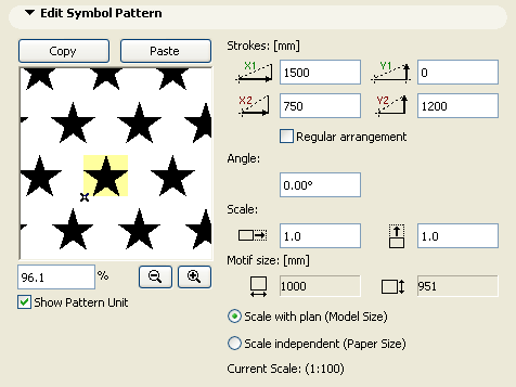
Fill Edit Symbol Pattern Panel
This panel appears in the Fill Types Dialog Box (Options > Element Attributes > Fill Types) if you are creating or editing a Symbol fill.
To create a Symbol fill, first draw a symbol unit in a 2D window and copy it. Then open the Fill Types dialog box. Click Paste in the Edit Symbol Pattern Panel to paste the copied symbol into the preview window.
For additional details, see Create or Edit Symbol Fill.

Show Pattern Unit: Check this box to place a highlight over the symbol unit in the preview window.
Strokes: Use these four fields to set the vectors of rows which compose the symbol pattern.
First note the Motif size of the symbol unit (shown at the bottom of this panel.)
•X1 and Y1: These values determine the horizontal (X1) and vertical (Y1) distance between the symbol units for the first vector of the pattern. For example, if the Motif size is 1000 mm, then an X1 value of 1500 for the vector pattern means that the symbol units are placed alongside each other with a 500 mm gap.
•X2 and Y2: These values determine the horizontal (X2) and vertical (Y2) distance between the symbol units for the second vector of the pattern. For example, if the Motif size is 1000 mm, then an X2 value of 750 means that the next row of symbol units is staggered back by 750 millimeters compared to the first horizontal vector (at 1500 millimeters).
Angle: Enter an angle in degrees if you wish to skew the fill pattern.
Scale: Enter scale factors by which to “stretch” the Symbol unit both horizontally and vertically. (By default, this factor is 1.0, that is, the symbol unit is not stretched.)
Motif size: These fields provide feedback on the absolute size of the Symbol unit on the Floor Plan.
The percentage field and the zoom buttons below the preview window refer to the image in the preview window only. The preview displays the symbol pattern at the given percentage as compared to its appearance on the Floor Plan.
To determine the relationship between fills and project scale, use the two radio buttons:
•Scale with plan (Model size): Use this option to ensure that the current Fill type will be displayed at the same scale as the model on every output.
Note: Avoid editing a scaled fill type if the project scale is different than that of the fill type, as it will be distorted.
•Scale-independent (Paper size): Use this option to display, plot and print the current Fill type definition at a fixed size, regardless of output scale.