
For a description of generic settings common to all tools in the Toolbox, see Working in Tool Settings Dialog Boxes.
The Slab tool is used for drawing and editing slabs, the basic horizontal building blocks of the Virtual Building.
For more information, see Slabs.
Slab Geometry and Positioning Panel
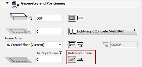
Slab Thickness: Enter a value for the slab’s thickness.
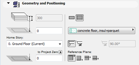
Note: If the structure of the slab is a composite, then the slab’s thickness is defined in Options > Element Attributes > Composites, and equals the sum of the skins’ thicknesses. A composite slab’s thickness cannot be edited in Slab Settings; you must go to Options > Element Attributes > Composites.
If you want to edit the slab thickness in Slab Settings, choose a non-composite (basic) slab structure.
Offset to Home Story: Define an offset for the Slab’s reference plane from its Home Story. The reference plane has several possible settings. (See Reference Plane.)
Choose one of the following Home Story settings:
•Current: The Slab’s Home Story will be the Current Story.
•Select Home Story: Choose a story to which to link the Slab. Click Select Story to bring up the full list of stories in the project, if they are not all shown in the list.
The Slab is physically linked to its Home Story. If you later modify the Home Story’s position (e.g. redefine the floor level), the Slab will change its position.
If you change a Slab’s elevation so that its reference plane is moved to a different story, you have the option to make the Home Story change to match the element’s new location.
See Change Home Story by Elevation.
For more information, see Home Story.
Offset to Reference Level: Define an offset for the Slab’s reference plane from the given Reference level (by default, this Reference level is Project Zero).
•The Slab reference plane has several possible settings.
See Reference Plane.
•Click the pop-up arrow to change the Reference level, if needed. Reference levels are defined at Options > Project Preferences > Reference Levels.
Note: This offset value serves as a calculation tool only, not a link. If you change the position of a Project Reference level, the Slab will not change its position.
Slab Structure
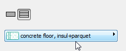
Click one of these icons to define the Slab as Basic or Composite, and then choose an attribute that reflects its structural properties:
•For a Basic Slab: use the pop-up to choose its Building Material.

•For a Composite Slab: use the pop-up to choose its Composite structure.

Note: This pop-up shows only those Composite Structures whose “Use With” control includes Slabs. Composites are defined at Options > Element Attributes > Composites.
By default, the Slab’s edge is perpendicular to its surface (90 degrees). If you wish to use a custom edge angle, click the corresponding icon and enter the angle in degrees in the field to the right.
Note: You can set a different custom edge angle for any single edge(s). If you have done so, a yellow “custom” icon appears alongside the edge type setting control in Slab Settings.
See Set Custom Slab Edge Angle and Edge Surface.
Depending on the structure you choose for the Slab (either a basic or a composite slab), you have varying options for the Slab Reference Plane:
•A basic Slab’s reference plane is either the top or the bottom of the Slab.

•A composite Slab’s reference plane can be one of four options: top of slab, bottom of slab; top of core, bottom of core.

Note: If the chosen composite structure has no core, then the core-related reference plane choices are greyed out.
Use the Info Box or Geometry and Positioning Panel of Slab Settings to choose a reference plane.
See also Slab Reference Plane.
Slab Floor Plan and Section Panel
Floor Plan Display
Show on Stories: Use the pop-up list to set the stories on which to show the Slab.
•Home Story only: The outline of the entire slab will be displayed and editable on its Home Story only.
•All Stories: The outline of the entire slab will be displayed on every story of the project.
•Other options are to display the slab on its Home story plus one story up and/or down.
•Custom: Choose this option if you wish to show the slab on any other combination of stories. The Show on Stories: Custom Settings dialog box appears, where you can set separate story display options for the slab outline and its fill.
Note: Fills can only be displayed on stories where the outline is also visible.
Note: The line type of slabs displayed on remote stories is set in Options > Project Preferences > Legacy.
For more information, see Show On Stories.
Cut Surfaces: In this section, set the attributes displayed for cut surfaces both in Section and on the Floor Plan.
•Define the cut line type and pen
•For either a basic or composite Slab:
•If needed, override the fill foreground/background pens of this element (defined by default in the Building Material). To do this, choose Foreground, Background or Both from the Override Cut Fill Pens pop-up to access the respective controls.

Outlines: These settings apply to the line type and pen color of slab outlines that fall below (Uncut) the Floor Plan Cut Plane.
•Overhead Lines will be displayed if the Floor Plan Display pop-up is set to “Projected with Overhead” or “Overhead All”.
•Uncut Lines will be displayed if the Floor Plan Display pop-up is set to “Projected” or “Outlines Only.”
Cover Fills: Check this box to display a cover fill using the fill and pen settings chosen here.
•Choose a fill type from the pop-up palette.
Note: Only those Fills defined as Cover Fills in Options > Element Attributes > Fill Types are available here.
•Choose pencolors for the cover fill pattern and for its background.
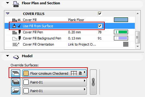
•Use Fill from Surface: Check this box if you want your cover fill to resemble the element’s top surface (vectorial 3D hatch), either as defined in the Building Material or (if the override is on) its top surface override

Cover Fill Orientation: This control defines the orientation of the fill pattern. Select the control, then choose an orientation definition from the pop-up opened with the black arrow:
•Link to Fill Origin: If you choose this option, then the cover fill will show a fill handle when you place the slab on the Floor Plan. You can then manipulate the fill orientation by selecting and moving the fill handle. (Use the “Move Sub-Element” command from the pet palette.)
Note: Fill handles are only displayed if you have enabled View > On-Screen View Options > Fill Handles.
•Link to Project Origin: The fill pattern will start at the Project Origin, and the part of the pattern that falls within the Fill’s boundary will be displayed. No fill handle appears.
•Distorted Fill: The Fill pattern can be distorted by altering the lengths and directions of its double fill handle.
For examples of each option, see Fill Orientation Methods.
This panel affects the 3D display of the slab.
Override Surfaces: Click the toggle button of any or all three pop-ups if you wish to override the surface assigned to this element (in its Building Material). You can override the surfaces of the Slab faces, and/or all Slab edges.
For a composite Slab, the “top” surface is the first listed skin of the composite, in Composite Settings.
Click the chain icon to assign the last surface chosen to all faces and edges. Deselecting the chain icon will restore the surfaces that you originally set for each face/edge.
Note: The chain icon is available when all the surfaces use overrides.
For more information, see Surfaces.
Note: The top-side surface override, if it is a vectorial hatching, can also be applied as a cover fill for the Slab (by checking the “Use Fill from Surface” box in Floor Plan & Section panel of Slab Settings). Moreover, if the cover fill has a customized fill origin (via Link to Fill Origin option), the 3D Model will reflect that fill orientation too.
Custom Edge Surface: If you have customized any of the Slab’s Edge surfaces (in the Custom Edge Settings dialog box), a yellow “custom” icon appears alongside the surface setting control in Slab Settings, indicating that one or more edge surfaces have been changed from the general setting.
See Set Custom Slab Edge Angle and Edge Surface.
Custom Texture defined in the 3D window: If this message is activated, it indicates that the currently selected slab (already placed in the project) has been assigned a custom 3D texture.
•In this case, the Reset Texture button is also activated. Click to restore the origin of the Texture of the selected slab.
For more information, see Align 3D Texture.
Slab Listing and Labeling Panel
See Listing and Labeling Panels.
Slab Tags and Categories Panel