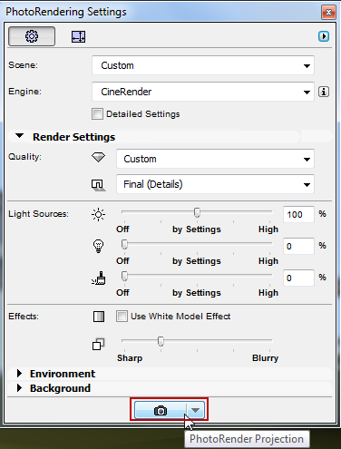
To create a rendered image of the 3D window contents, subject to render size settings:
•Click the render icon at the bottom of the PhotoRendering Settings Palette, or
•Use Document > Creative Imaging > PhotoRender Projection

•The picture window appears, with a progress bar and Stop button, feedback on elapsed rendering time, plus the familiar Zoom and Fit in Window window controls.
•In Tab Bar, Picture window tab shows feedback on background rendering progress (CineRender only). A checkmark indicates that the render is complete (but not yet opened).

Rendering in progress

Rendering complete, not yet viewed
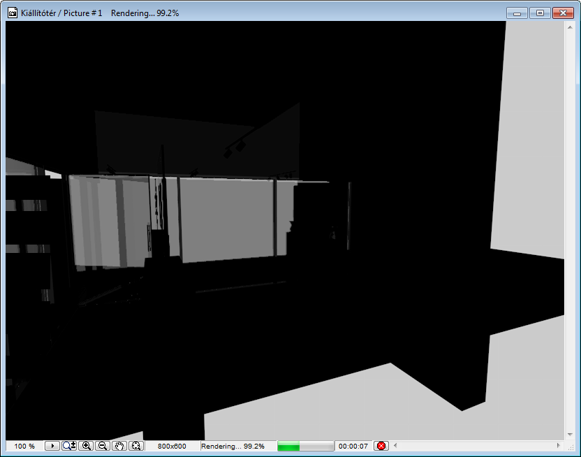
•If needed, click Stop, or just close the window to stop the render.
Note: Rendering time varies depending on many factors, including size and complexity of the rendering parameters, and hardware capabilities.
By placing a Marquee in the 3D window, you have additional ways to limit the rendered model.
Note: You must use the 2D Marquee option. It will always assume a rectangular shape (even if you draw a custom-shaped Marquee.
Once you have placed the Marquee, two Render Region commands are available (in the Document > Creative Imaging menu and as pop-up options of the Render button of the Render palette):
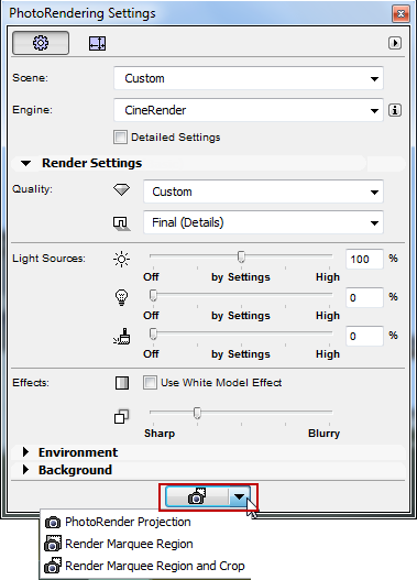
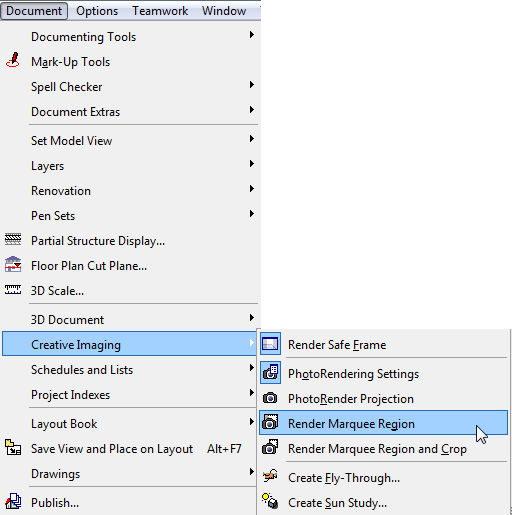
•Render Marquee Region and Crop: With a Marquee placed, this is the default rendering command. This renders and outputs only the marquee region.
•Render Marquee Region: Use this function if you only want to render a small part of the 3D window. It will render the scene as a whole, but only the marquee region is rendered in full; the rest of the scene is shown as transparent.
This is useful, for example, if you have already fully rendered the scene, but then change or correct one small part of it, and only need to re-render that part.
For either option, the Preview shows only the marqueed region.
Note: If the Render Safe Frame mode is on (see below), then your Marquee will only have an effect to the extent that it falls within the Render Safe Frame. If Render Safe Frame is off, then you will render the Marquee area regardless.
Turn on this 3D view feature at Document > Creative Imaging > Render Safe Frame.
This is an ARCHICAD mode that affects the 3D window; it displays a frame that indicates which part of the model will be rendered.
This might not be obvious, because the output is affected by the Size setting in Render Settings. Depending on the Size settings, your model could be cut off in the render.
See Set Size.
The Render Safe Frame gives you feedback on this and a chance to adjust the Size parameters.
Note: The Render Safe Frame setting to OFF corresponds to Rendering Settings from ARCHICAD versions 17 and older. In this situation, the full content of the 3D window - even content that is not visible on screen - will be rendered, with its size determined by Render Size.
This setting (whether Render Safe Frame is applied or not) is noted in the 3D Only panel of View Settings and on the 3D Visualization toolbar.

Phases of Rendering with CineRender
Although the CineRender engine is built in to ARCHICAD, it is an add-on that is a separate program component. The rendering process involves data exchange between the ARCHICAD model and the engine, in the following steps:
1.Converts the 3D model. This occurs in ARCHICAD; this goes quickly, but during this time you cannot continue working in ARCHICAD. During this interval, you will see the “Preparing” tag in the top right corner of your screen in a separate Progress Window, and also and in the rendering window.
2.Model is sent to the CineRender engine. This takes only a few seconds. To optimize the process, only those changes are sent which occurred since the last render.
3.Rendering calculations are underway. During this time, you can keep working in ARCHICAD.
Meanwhile:
•Global Illumination (if applied) is calculated. You can recognize this phase by the sampling on the picture, while the lighting of the scene is calculated.
•The rendering itself takes place, recognizable by the squares revealing the image from the inside out, in a circular manner. Note that the number of squares corresponds to the number of cores in your computer (more cores result in faster renderings)
•Finally, post effects (if applied) are calculated.
4.The Render picture is sent back - this is an ongoing process whose progress you can see in the picture window.
Export to Cinema 4D
The CineRender engine in ARCHICAD does not support multi-pass or net render functions. If you want to continue working on your model with additional Cinema4D functions, use the Export to Cinema 4D command from the Render pop-up button of the PhotoRendering palette. This will export your model, surfaces and rendering settings.
However, to improve the post-processing of images, it is possible to save model pictures with a color depth of 32-bit per channel in certain image file formats (e.g. TIF).
Note: This color-depth feature is not available if the model picture is created using the Render Region & Crop command, which creates the image using only 8 bits per channel.
Limitation on Axonometric 3D Views Handled by the CineRender Engine
The following axonometric views in ARCHICAD are not supported by the CineRender engine:
•monometric axonometry
•custom axonometry (if the Z-axis is not vertical, or if the x-y axes have been distorted)
See Parallel Projection Settings.
If you are working with such a 3D view in the Photorendering environment, you will be alerted to the problem and options for resolving it: both in the Photorendering Preview, and during the final Photorendering process itself.
In the Preview window:
The preview window will display a warning notice:
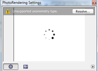
Click Resolve to bring up further information:
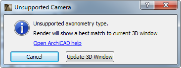
The preview will be generated using a “best match,” that is, the view axes will be modified as needed to achieve an axonometric view that the CineRender engine can handle.
You have two options here:
•Click Cancel to proceed - the Preview and the 3D view will not be totally identical, because the Preview will show a “best match”.
•Click Update 3D Window to modify the 3D view to match the view in the Photorendering Preview.
During the final PhotoRender
The following dialog box appears:
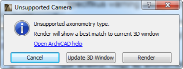
Choose one of the following options:
•Click Render to continue the rendering process. CineRender will create a rendering using a “best match,” that is, the view axes will be modified as needed to achieve an axonometric view that the CineRender engine can handle. Thus, the final rendering will correspond to the Preview, but the 3D window remains unchanged.
•Click Update 3D Window to modify the 3D view to match the view in the Photorendering Preview. (If you are not satisfied with this modified view, you can adjust it as needed.) The rendering will not take place until you issue the PhotoRender Projection command again.
•Click Cancel to end the process without rendering.