
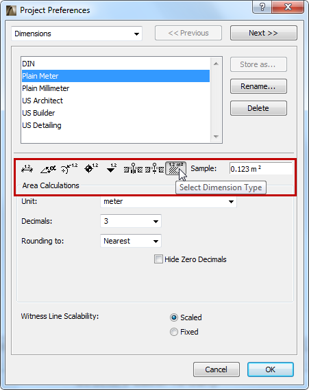
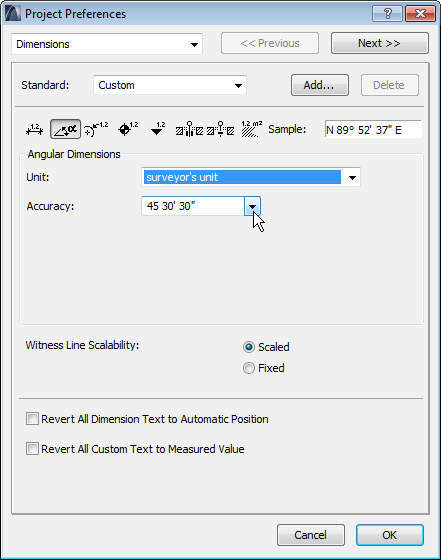
To access this screen, go to Options > Project Preferences > Dimensions.
The available dimension options will vary depending on the unit (metric or imperial) you choose, and on the dimension type whose preferences you are setting.
See also Dimensioning.
Choose Dimension Standard for Project
From the list on the Dimensions page of Project Preferences, select a dimensioning standard (e.g. Plain Meter).
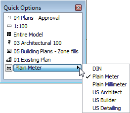
For a quick way to change the dimension standard of your project, use the Dimensions pop-up in the Quick Options Palette.
Vary Dimension Standard by View
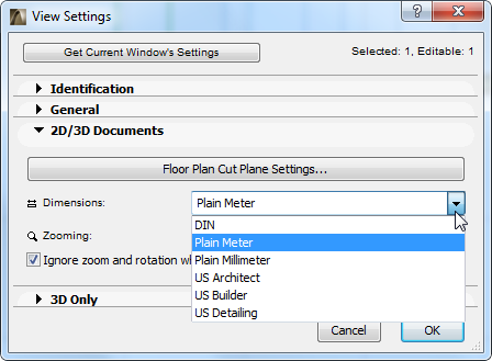
While the Dimension Standard set here applies to the Project globally, you can apply a different dimension standard to any view of the Project, if needed.
To change the dimension standard for any single view, go to the 2D/3D Documents panel of View Settings and change the Dimension standard.
Store Custom Dimension Standard
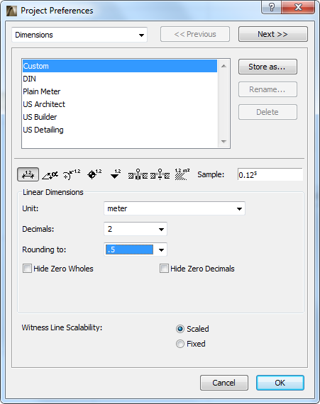
Store As: If you have customized a dimension setting in this dialog box, the Standard name changes to “Custom.” Click “Store as” to name this customized Standard and make it available to your project as a named Standard.
Delete: Click this button to remove the selected Standard from the list.
Click one of the 8 icons to choose the dimension type whose options you wish to set:
•Linear
•Angular
•Radial
•Level
•Elevation
•Door/Window/Skylight
•Sill Height
•Area Calculations (including area displayed on Zone Stamps)
Unit: Define the Unit for each of the Dimension types.
Sample: Feedback on the chosen unit display format.
Unit Display
The options displayed depend on the Dimension Type you have chosen. They can include:
Decimals: Define the number of Decimals you want to display in each dimension value.
Rounding to: Click a rounding option from the pop-up field if you want to display additional decimal values as a superscript.
For example, here the number of decimal places is set to two; but Rounding is set to .5, so the next decimal value is also displayed, as a superscript, and rounded to .5. See the result in the Sample field of the dialog box.
Hide Zero Wholes: Check this box to suppress whole zero values:
Example:
•0.25 meters is displayed as 25
•25 meters is displayed as 25.00
Hide Zero Decimals: Check this box to hide any zeros at the end of the decimal dimension, regardless of the number of decimal places you set in the Decimals popup above.
You cannot use the Hide Zero Decimals options concurrently with Hide Zero Wholes.
Accuracy: Click this pop-up field to select the precision if your chosen Angular Dimension Unit is degrees/minutes/seconds or surveyor’s unit.
If you choose an imperial unit, the following other options may be available.
Note: You cannot mix units for the same dimension type in a Project. However, you can display two types with the Secondary Dimensions command.
Fractions: Click this pop-up field to define the fractions displayed for the selected Measurement Unit, if you are using a unit that includes fractional inches.
Fractions in Small Type: Toggles printing of fractional inches and feet in small characters on and off in length dimensioning.
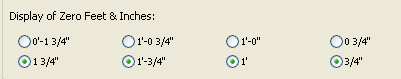
Display of Zero Feet & Inches: If using Feet & fractional inches, this section has three pairs of radio buttons; if using fractional inches, there is one pair of radio buttons. For each pair, choose the option you prefer for displaying dimensions that measure either zero feet or zero inches.
Witness Line Scalability: Choose either fixed or scaled to make your witness lines keep a fixed scale, or else vary them depending on window scale. (Witness lines are the perpendicular lines between a dimension and the dimensioned element.)