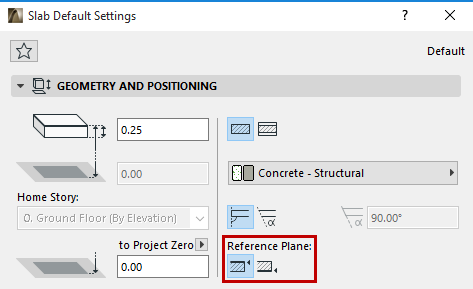
Each Slab has a reference plane which plays a role in intersections with other elements. The ability to flexibly assign a Slab reference plane helps you to align intersections easier and to control the changes that result if you alter the Slab structure.
See Use Cases, below.
If you redefine an existing Slab’s reference plane, the entire Slab will change its position accordingly. This way, the connections previously made to the slab will remain intact.
Note: To modify the Slab reference plane while keeping the Slab position unchanged, use the Modify Slab Reference Plane command.
See Modify Slab Reference Plane, below.
Use the Info Box or Geometry and Positioning Panel of Slab Settings to choose a reference plane. Click the “C” shortcut to cycle through the reference plane options in the Slab Info Box.
A basic Slab has two possible reference planes: either the top or the bottom plane.

A composite Slab has four possible reference planes: the top or the bottom of the Slab core, or the top or bottom of the Slab.
Note: If the chosen composite structure has no core, then the core-related reference plane choices are grayed out.
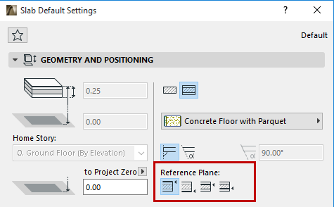
For a composite Slab, the “top” surface is the first listed skin of the composite, in Composite Settings.
Notice that the Info Box elevation icons and fields vary depending on the location of the Slab’s reference plane.


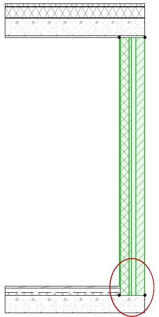
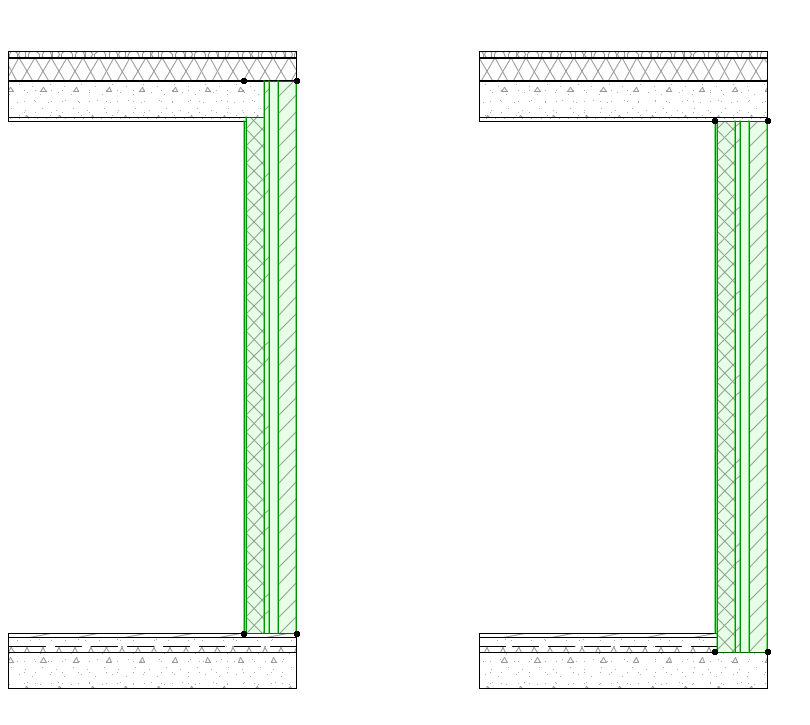
Thus, Walls can join Slabs by connecting to the top of the slab core, rather than the top of the Slab finish.
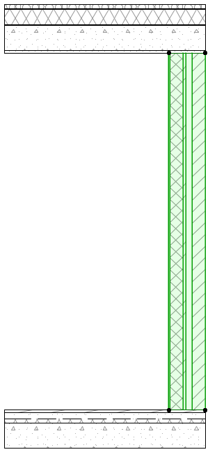
•When a Slab is used to model a ceiling: the reference plane can be placed at the Slab base, rather than the top.
•If you redefine an existing Slab’s Reference Plane from Core Top to Core Bottom, the entire Slab will change its position accordingly. This way, the connections previously made to the slab will remain intact.
Here, the Walls are connected to the Slab’s Core Top and Bottom, respectively.
Reference Plane in Interactive Schedule/Find & Select
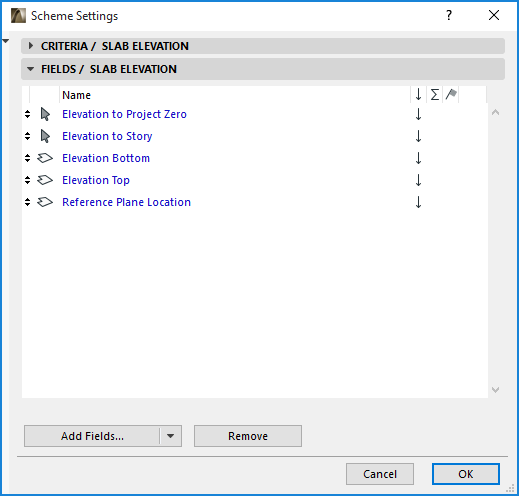
In the Interactive Schedule, you can list Slab elements using separate fields for the element’s top and bottom elevation; but the “Elevation to Project 0” and “Elevation to Story” refer to the elevation of the Slab reference plane (not the elevation of the Slab top).
It is also possible to Find & Select slabs in your project, or list them in the Interactive Schedule, based on the position of their reference planes:

Editing Slabs by Reference Plane
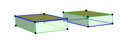
In 3D view, the Slab Reference Plane is shown as a thick blue line. Its shape is a projection of the top of the Slab; to edit the Slab, you can click either on the Reference Plane line or the Slab’s top outline, or any of the nodes.
Use this function (Edit > Reshape > Adjust Elements to Slabs) to easily adjust elements (Walls, Columns or horizontal Beams) to specific levels of one or more Slabs that are located above and/or below them.
This command (at Edit > Reference Line and Plane > Modify Slab Reference Plane) enables you to modify the Slab reference plane of one or more selected Slabs, while keeping the Slab position unchanged.
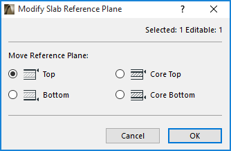
Note: If the selection includes one or more basic Slabs, then choosing the “Core Top” option here will result in a “Top” reference plane for these basic Slabs.
This function can be helpful if you use basic structures to model during the sketching phase, then later convert basic Slabs to composites. In such a case, you can adjust the reference plane to the core top rather than the top, as needed.
When migrating older-version files, you may find it useful to use this function to change the Slab reference plane from the top to other locations.