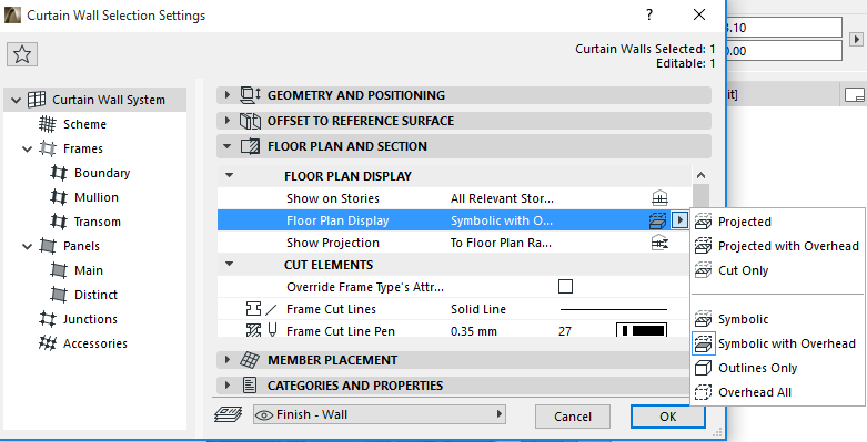
Curtain Wall display in Floor Plan and Section views is defined in Curtain Wall Settings.
Note that the Curtain Wall’s default Floor Plan Display option is called “Symbolic with Overhead,” which is unique to Curtain Wall Settings.
In Symbolic with Overhead, Frame and Panel elements are depicted using symbolic display. The Curtain Wall’s 3D model is displayed as cut at the level of the Floor Plan Cut Plane, plus the Curtain Wall’s overhead part (the part above the Floor Plan Cut Plane), and its uncut (downward) part.
In Symbolic with Overhead mode, Accessories and Junctions are not shown at all on the Floor Plan, and only the Frame centerlines are displayed.
The Symbolic or Symbolic with Overhead options are recommended for regular, vertical Curtain Walls. For other geometries, the Projected options will work better.
Model View Options for Curtain Walls
Go to Document > Model View > Model View Options. In the Options for Construction Elements panel, choose one of the two preferences for displaying Curtain Walls. These will affect the display of Curtain Walls in the 3D, Section-type and 3D Document windows only:
•Full: Panels and Frames are displayed in the Curtain Wall.
•Schematic: Only the Scheme (Gridlines, Boundary, Reference Line) is displayed.