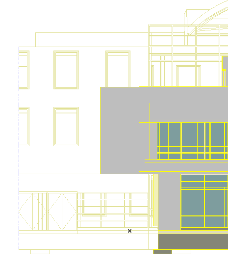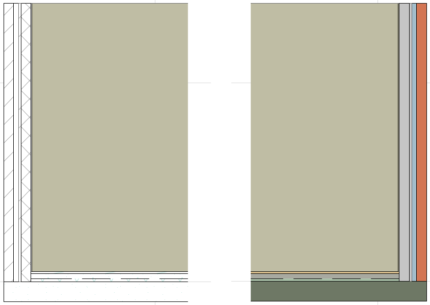
Model Display in the Section Window
Note: The controls for the display of elements is nearly identical for Elevations and Interior Elevations, and for 3D Documents based on the Floor Plan.
Controls of the Model Display panel in Section Settings define the appearance (fills, contours, surfaces) of:
in the Section window.

The following are brief descriptions of these display features.
For an individual description of each control, see Section Model Display Panel.
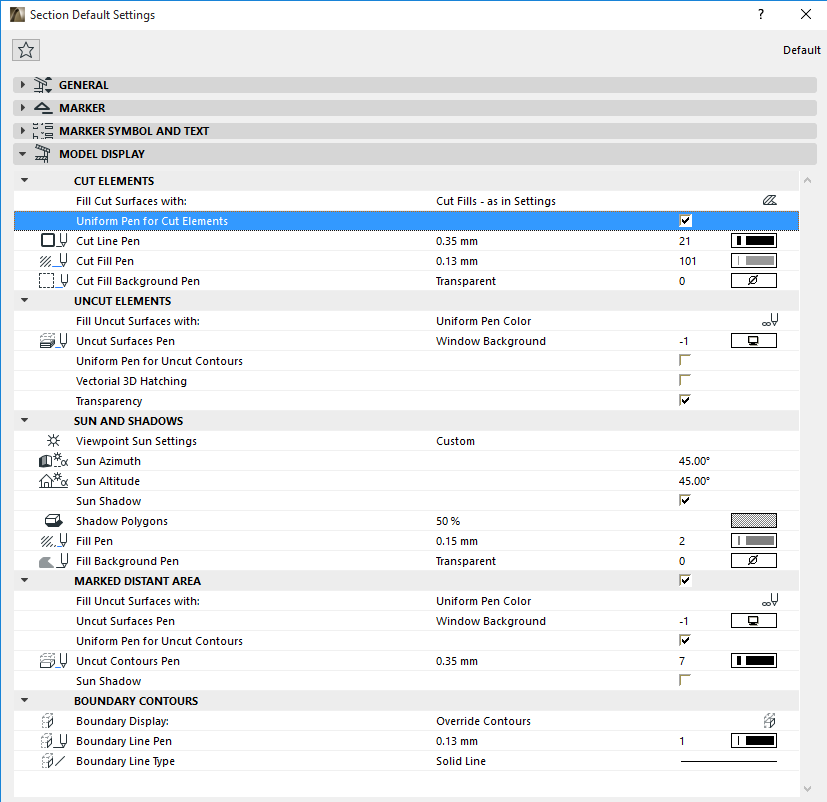
By default, cut elements are shown using their element-level line and pen definitions. You can customize the appearance of cut elements in a Section window by checking the Uniform Pen for Cut Elements checkbox in the Model Display Panel of Section Settings, then assigning the lines and colors, for the display of cut elements in this Section only.

Surface colors and vectorial hatching can be displayed only on uncut surfaces of elements in the Section/Elevation/IE windows.
These options in the Model Display Panel of Section Settings enable you to apply surfaces (shaded or unshaded) to the uncut elements shown in the Section window:

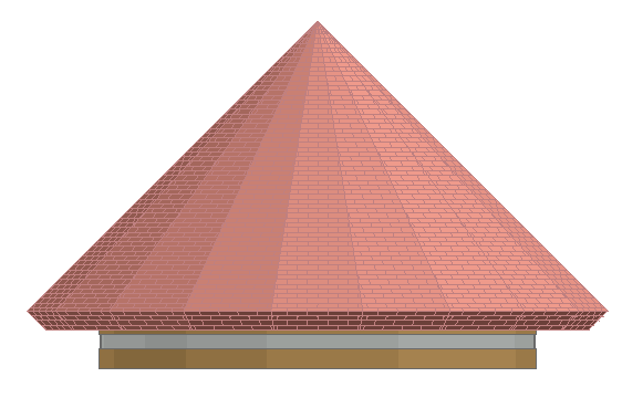
The following elevation is displayed with Vectorial Hatching “on” (as shown by the brick wall) and with Sun Shadow “on” (as shown by the shadow cast by the roof overhang.)

Another effect is to display uncut surfaces in “shaded” mode - that is, to reflect rounded contours. You can combine the two effects (cast shadows and shaded effect) in a single Section display:

Consider the following Section line on the Floor Plan:

Note that this Section includes the west face of the building, close to the section line, as well as parts of the far end of the building that extends northward. In this Section view, the close and distant areas are displayed identically, so you cannot tell which is which:

To differentiate the “close” from the “distance” elements, reconfigure the section so that it contains a Marked Distant area: check the Marked Distant Area box in the in the Model Display Panel of Section Settings and specify a different color for the contours of the “distant” elements.
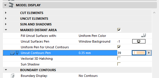
Return to the Floor Plan and notice that a new line segment representing the Distant Area has appeared.
Select this line and drag it as shown:
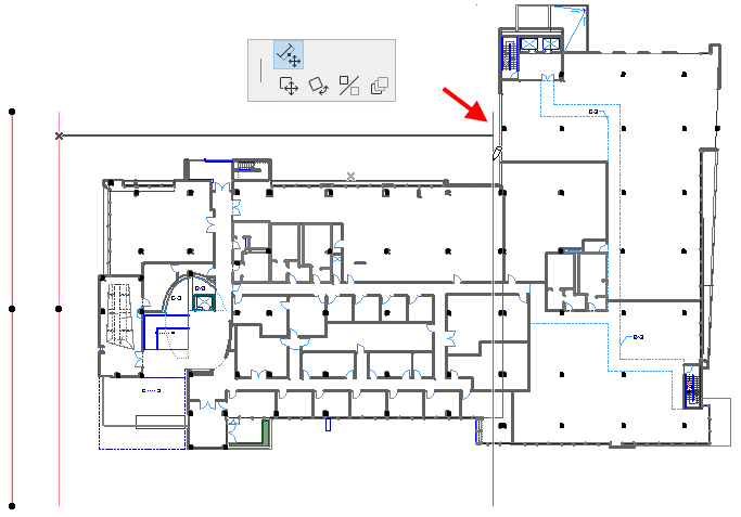
Note: The Distant Area line is a “Marker Range Line”.
See also Display of Marker Range Lines.
Now re-open the Section. The distant elements are distinguished from the closer ones.
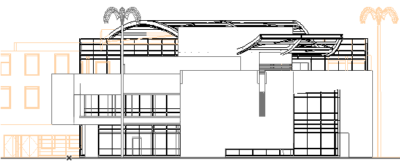
“Boundary Contours” refer to elements shown in the Section, Elevation or Interior Elevation window which extend beyond the horizontal limits of the Section (in other words, the entire element does not “fit” in the section window).
Use Boundary Contours in the in the Model Display Panel of Section Settings to define the display of this boundary.
Here, the left edge of the wall on the left does not fall within the section, and the displayed parts are shown as unfinished, without contours.

However, you can choose to display boundary contours - that is, to draw a line at the element’s boundary as it is shown in the section, even though the element does not really end there. At Boundary Display, choose “Uncut Contours” to display these contours using the uncut pen chosen for these elements in their own Settings dialog boxes; or “Override Contours” to use a pen of your choice:

