Vertical and Horizontal Range of the Interior Elevation
The Horizontal Range can be either Infinite or Limited.

The default choice is Limited. In this case, the IE view will extend horizontally until the Room Boundary line.
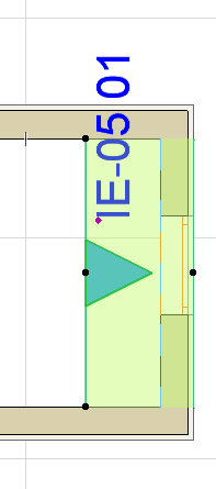
If the Room Boundary is a Wall, then the view automatically extends to the depth of the Wall; you can see this by the Marker Range highlight, which overlaps the Wall area.

To adjust the horizontal range, select the Room Boundary line and stretch or shrink it using the commands of the pet palette. (Stretch/shrink modifications to this segment will affect the neighboring line segments accordingly, as when editing any polyline.)
An Infinite Horizontal Range means that the Interior Elevation viewpoint will extend horizontally to include all visible parts of the model.
Add Bounded Areas (Interior Elevation Default Settings)
To include connected enclosed areas in the Interior Elevation viewpoint, choose Add bounded areas. This checkbox is available
•in Interior Elevation Default Settings (you must set it before you place the IE; you cannot set this control for an already placed IE)
•if the Limited option is checked for Horizontal Range

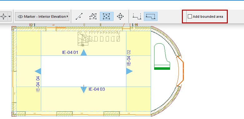
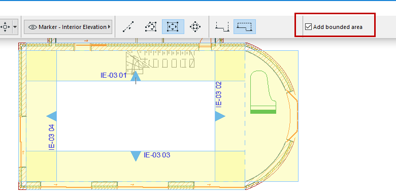
This way, if the room contains an odd-shaped alcove, the IE viewpoint will include structures that fall beyond the Room Boundary Line, but still fall inside the room.
The following two illustrations show the result of the checkbox setting:


Vertical Range
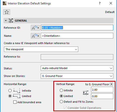
An IE viewpoint’s vertical range is set manually by the user in the General Panel of Interior Elevation Settings, or the Info Box.
See Interior Elevation (IE) Tool Settings.

Each IE view (i.e. each segment of the IE Room Boundary polyline) can have a separate, custom vertical range value, if desired: choose the Limited option as the Vertical Range and enter the desired elevation limits.
Use the pop-up to define whether this vertical range should be measured from Project Zero, or from the Interior Elevation’s Home Story (the story onto which it was placed).

If you want the Interior Elevation geometry to correspond to a zone, choose the Detect and Fit to Zones Vertical Range option from the General Panel of Interior Elevation Settings.

If a zone is detected, its height will be used as the vertical range of the selected Interior Elevation viewpoint.
Zones edited by Solid Element Operations are also calculated accurately, provided that you also check the Consider Solid Operations box. For example, a single zone trimmed to a slanted roof will have several different zone heights. These are accurately reflected in each viewpoint of the Interior Elevation group.
