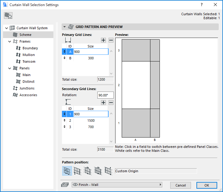
Curtain Wall Settings: Scheme Page
The controls in this dialog box define the grid pattern and grid properties.
In Curtain Wall System Settings, the Scheme page sets the System-level default settings for Schemes.
Scheme Tool Settings contains identical controls. Scheme Tool Settings is available in Curtain Wall Edit mode only. Use the Class pop-up to apply System-level Scheme settings to the selected Curtain Wall. If you customize any parameters in Scheme Tool Settings, the Class pop-up will show “Custom.”
Curtain Wall Settings: Scheme Page: Grid Pattern and Preview Panel
Use these controls to define the pattern of the Curtain Wall grid, in its primary and secondary directions. This grid will determine the size and arrangement of the Curtain Wall panels.
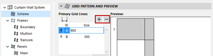
Primary Gridlines: Use these controls to define the grid pattern in the Primary direction.
Important: The “Primary” grid direction of any Curtain Wall is determined when you first create the Curtain Wall: the primary direction will always be perpendicular to the input vector. For example, if you create a Curtain Wall that is extruded from a polyline, the primary grid direction for each Curtain Wall segment is the direction perpendicular to the polyline segment. If you create an arced Curtain Wall, the primary grid direction is the same direction as the Curtain Wall surface created by extruding it from the input arc.
Each panel field in the primary direction is given an alphabetical ID (A, B, ...)
Enter a value for the length of the panel field in the primary direction. Notice how the Preview image changes accordingly.
To create a new panel field, click the Plus sign next to the “Size” field.
To delete a panel field, select it in the list, then click the black Minus sign.
Total size: This item gives you feedback on the total length of the grid pattern in its primary direction.
Secondary Gridlines: Use these controls to define the grid pattern in the Secondary direction.
Important: The “Secondary” grid direction by default is perpendicular to the Primary grid direction (i.e. rotated 90 degrees). However, you can set a rotation angle (20 to 160 degrees) for the Secondary gridlines, relative to the primary gridlines.
Rotation: Enter a Rotation value for the Secondary Gridlines relative to the Primary Gridlines.
Note: Even if you alter the Rotation angle, this will not be reflected in the Preview window, but it will be applied to the Curtain Wall.
Each panel field in the secondary direction is given a numerical ID (1, 2, ...)
Enter a value for the length of each panel field in the secondary direction. Notice how the Preview image changes accordingly.
To create a new panel field, click the Plus sign next to the “Size” field.
To delete a panel field, select it in the list, then click the black Minus sign.
Total size: This item gives you feedback on the total length of the gridline pattern in its secondary direction.
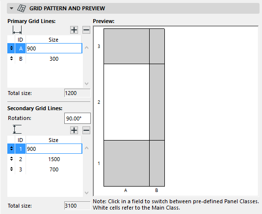
The Preview window gives you a preview of your grid pattern and the alternating panel classes. Use the Preview window to define the panel class associated to each panel in the pattern.
Clicking on any panel in the preview window toggles the panel between gray and white.
•White means the panel will belong to the “Main” class.
•Gray means the panel will belong to the “Distinct” class.
The properties of these panel classes (Main, Distinct) are defined in the Panel (Distinct and Main) dialog boxes of Curtain Wall System Settings.
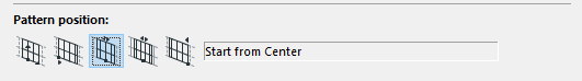
Use this control to determine where to place the origin of the grid/panel pattern (defined above) on the Curtain Wall Reference line segment.
•For a Curtain Wall with a plane or cylindrical base surface, the “Reference line segment” is the first vector or arc you draw when defining the surface.
•For a Curtain Wall based on an extruded profile, each segment of the reference polyline is considered separately: the pattern position chosen here will be applied separately to each of the Curtain Wall segments.
Choose one of the following Pattern position options.
•Custom Origin: This option will enable you to graphically move the grid pattern in its primary direction, after you have placed and selected the Curtain Wall.
The next four options will lock the origin of the grid pattern to a specific reference point on the Curtain Wall. (Only the Primary grid is locked; the Secondary grid will remain editable.)
•Start with Segment: The grid pattern will begin at the start of the reference segment.
•Start from Center: The grid pattern will begin at the center of the reference segment, and will be distributed in two directions, on each side of this center. (This option means that the center of the Curtain Wall will always have a gridline running through it.)
•Align to Center: The center of the grid pattern will be placed at the center of the reference segment.
•End with Segment: The grid pattern will begin at the endpoint of the reference segment.