This command is available in different forms depending on the selected items:
For Selected Construction Elements
For Placed Drawings (Source is not a PDF)
For Placed Drawings (Source is a PDF)
For Selected Construction Elements
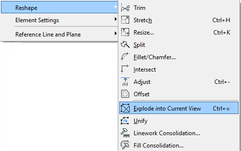
Choosing Edit > Reshape > Explode into Current View will turn selected elements (Floor Plan and other 2D windows only) into 2D drawing primitives (Lines without arrowheads, Circles, Arcs, Elliptic arcs, Splines, unframed Fills, single-line Texts).

In the appearing dialog box, you have the option to keep original elements. If you uncheck this box, the original elements will be deleted, and only the exploded primitives will remain in the project.

Note: The Explode command will not affect grouped or locked elements. Turn on Suspend Groups before exploding grouped elements.
Note: If you explode a construction element with the “Keep Original Elements” box unchecked, then that element will no longer exists as a construction element. Consequently, it will disappear from other model views (model-type Sections, Elevations, IEs, 3D Documents).
Some examples:
•Slabs, Roofs and Meshes are exploded into lines
•Walls and Columns are exploded into Lines and Fills (Doors and Windows inserted into Walls are also exploded)
•Doors and Windows (if selected without the Wall they are placed into) are exploded into 2D elements and replaced by empty hole openings
•Dimensions are exploded into Lines, Texts and the basic elements of arrowheads (Lines, Circles, Arcs, Fills)
•Polylines are exploded into Lines and Arcs
•GDL Objects are exploded into basic 2D drawing elements
Explode has no effect in the following cases:
•In Section/Elevation/IE and 3D Document windows, cut construction elements cannot be exploded
•Section/Elevation/IE lines and Cameras
•Basic 2D elements
For Placed Drawings (Source is not a PDF)

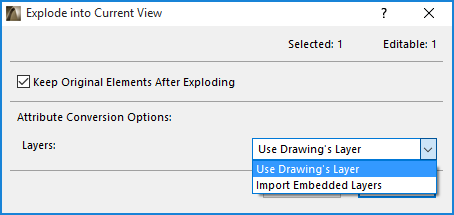
This dialog box appears if you select and explode a Drawing that has layers (that is, if it is a DWG file or if it is derived from an ARCHICAD view), and does not have a PDF document as its source.
Attribute Conversion Options
Note for Teamwork users: If you choose an option that creates new attributes, you must first have the needed access right (e.g. Create Layers). If you do not have the right, a warning appears, and the option is grayed out.
Choose the Layer on which to place the drawing primitives that will result from the Explode:
•Use Drawing’s Layer: All resulting drawing primitives will be placed on the same Layer as the Drawing is on.
•Import Embedded Layers: This option means that the drawing primitives will be placed on layers corresponding to their layer assignment in the Drawing source (e.g. DWG file). Those embedded layers will be imported into your ARCHICAD project.
For Placed Drawings (Source is a PDF)

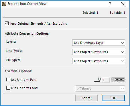
This dialog box appears if you select and explode a Drawing that has a PDF document as its source. The Attribute Conversion and Override options allow you to control the appearance of the resulting elements. However, be aware that the elements from the PDF might not look exactly the same after Explode - e.g. what appears to be a fill in the PDF document may be composed of lines, and will be exploded as lines in ARCHICAD.
Watch the Video:
Flexible PDF Editing Options
Attribute Conversion Options
Note for Teamwork users: If you choose an option that creates new attributes, you must first have the needed access right (e.g. Create Layers). If you do not have the right, a warning appears, and the option is grayed out.
Layers: Choose the Layer on which to place the drawing primitives that will result from the Explode:
•Use Drawing’s Layer: All resulting drawing primitives will be placed on the same Layer as the Drawing is on.
•Import Embedded Layers: This option means that the drawing primitives will be placed on layers corresponding to their layer assignment in the Drawing source (the PDF document). Those embedded layers will be imported into your ARCHICAD project.
Line Types: Choose a method for defining the drawing primitives’ line types.
•Use Project’s Attributes: No new Line Types will be imported from the Drawing’s source file; the project’s existing line types will be used. If there is no perfect match, then the drawing primitives will use the one of four basic Line Types - solid, dashed, dotted-and-dashed, or dotted - which corresponds to the exploded element’s original Line Type.
•Substitute With Similar: New Line Types are imported only if the drawing primitive does not correspond to any of the four basic Line Types.
•Import All: All Line Types from the PDF source are imported and added to the ARCHICAD project attributes.
Fill Types: Choose a method for defining the drawing primitives’ fill types.
•Use Project’s Attributes: No new Fill Types will be imported from the Drawing’s source file. Any fills in the drawing primitives that have no counterpart among the project’s attributes will be transformed into solid fills.
•Generate Symbol Fills: For any fills in the drawing primitives that have no counterpart among the project’s attributes, a new vectorial fill attribute will be created.
◦Vectorial fill patterns will be transformed to symbol fills without any text or image
◦Text or image content and gradient fills will be transformed into image fills
•Generate Image Fills: For any fills in the drawing primitives that have no counterpart among the project’s attributes, a new image fill attribute will be created.
Note: If an image fill is generated, then an image file is added to the project’s Embedded Library. If you are working in a Teamwork project, you must have the needed access right: Library Parts - Create.
Override Options
•Use Uniform Pen: Check this box to use a single pen defined here for all texts, fill contours and lines.
•Use Uniform Font: Check this box to use a single font defined here for all texts.
Fine-Tune View After Explode
After an Explode function, you may wish to fine-tune the view before final output.
You will find that the “exploded” lines and fills often contain superfluous elements (extra line segments, overlapping or superfluous fills) that make such editing difficult. To make editing easier, first use the Linework and Fill Consolidation functions on selected items in the window.
For more information, see Consolidate Lines and Fills in Drawing Windows.