

As a rule, set the Stair’s Turning Type (Landing or a Winder) in Stair Settings, and define its options. The selected Turning Type is placed at each turning (each point you click while placing the Stair baseline), between any two Stair Flight segments.
All Turnings will thus have the same settings. However, for a placed Stair, you can customize each Turning type separately.
See Edit a Stair’s Turning Type, below.
Define Turning Type in Stair Settings
In Stair Settings or the Info Box, choose a preferred Turning Type for the entire Stair.
•Landing
•Winder with Equal Angles
•Winder with Equal Goings
Note: In the USA version of ARCHICAD, “Goings” are known as “Runs”.
For each type, click the pop-up to adjust its specific settings. The settings differ for each Turning Type:
Winder with Equal Angles: Turning Type Options
Winder with Equal Goings: Turning Type Options
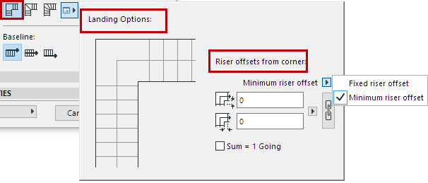
•Set the Landing offsets (for Lead and Trail Edge, respectively) from the corner.
•Define the offsets as either Fixed or a Minimum. (If you pick Minimum, the program will have some leeway to increase the offset, to fit the Stair input geometry.)
•Click the chain icon for a symmetrical landing (same offsets on both ends).
Note: The chain icon will ensure a symmetrical landing for each turning of the Stair. However, a Stair with multiple landings may use different offset values at different landings (if offset values are defined as a “minimum” rather than fixed).
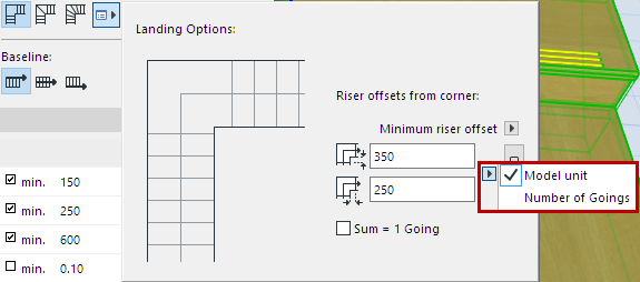
•Define the offset value in terms of either Model Units, or as a certain number of Goings.
Winder with Equal Angles: Turning Type Options
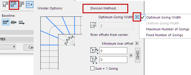
Set Division Method
Choose a method for dividing the Winder:
•Optimum Going Width: The program automatically finds a Going Width for the Winder which is as close as possible to the Going Width on the Stair’s straight flight.
•Maximum Number of Goings: The program automatically inserts the maximum number of goings into the Winder, within the limits of the current Stair Settings.
•Fixed Number of Goings: In the field below, enter a fixed number of Winder divisions. The Winder will be divided accordingly, regardless of any other rules set in Stair Settings.
Just as for the Landing, set riser offsets at either end of the winder, defined as a fixed or minimum value.
See Riser Offsets from Corner, above.
Winder with Equal Goings: Turning Type Options
Note: In the USA version of ARCHICAD, “Goings” are known as “Runs”.
The Winder with Equal Goings has four types to choose from. In all four types, the Going value of each winder is equal to the Going value of the Stair’s straight flight.
Notes:
◦Within a single Stair, all the Equal-Going Winders always use the same Winder Type (e.g. all are “Two Point” winders).
◦For an Equal-Going Winder, you can offset the Calculated Walking Line, which affects Going depth. See Offset Walking Line on Turning (Winder with Equal Goings)
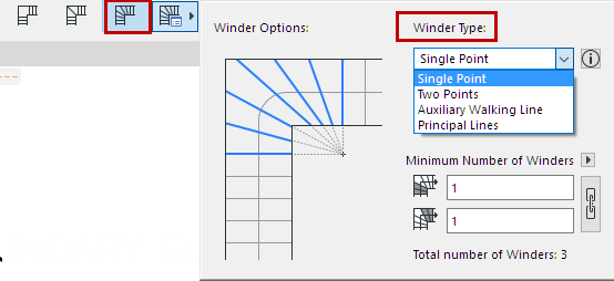
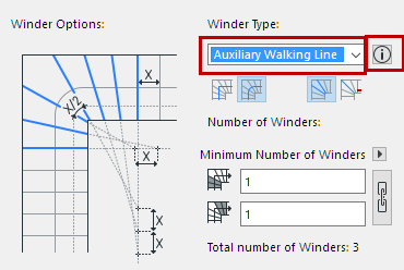
Winder Type
Choose one of four types of Equal-Going Winders from the pop-up.
The four winder types here differ in how the winders are constructed. For each, consult the illustrations in the dialog for an indication of how it works.
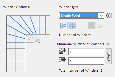
•Single Point: The lines of each winder converge at a single point. (This point is where the lines of the two adjoining straight risers intersect).
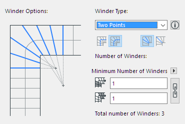
•Two Point Winder: The lines of each winder converge at one of two different points. (Location of these points: Take the lines of the two adjoining straight risers, and intersect them with the middle riser’s line (or the middle tread’s two lines).
See also Tread in the Middle/Riser in the Middle, below.
The following two winder types are based on a complex geometry, explained more fully in the linked article (click the information button to access it).
See the Help Center article on Winder Types:
•Auxiliary Walking Line Winder and Principal Lines Winder

Walking Line: Straight or Curved
Choose either Straight or Curved Walking line.
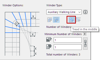
Tread in the Middle/Riser in the Middle
Choose either Tread in the Middle or Riser in the Middle. Note the difference in the illustration.
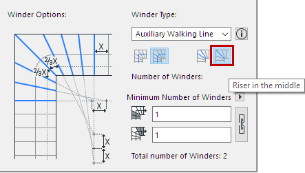
Number of Winders
Enter the number of winders above and below the middle Riser (or Tread). The resulting total is shown below.
Click the chain icon to create an equal number of winders above and below.
Notes:
◦When using “Tread in the Middle”, the number of winders below/above are added to this middle tread.
◦If you define your numbers as a “minimum” rather than “fixed”, the actual number of winders may vary from the total shown here.
Turning Type vs Segment Type
Stair segments - not just Turnings - can be defined as Landing or Winder-type segments (as well as Flight segment). Segment type is set not in Stair Settings, but on the fly, during Stair input.
See Stair Segment Type.
These Segment definitions can produce different Turning Types than the one you set in Stair Settings.
In any case, you can customize Turning Type options - for any particular segment or any particular Turning - after Stair input.
See below.
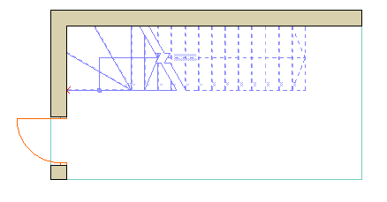
For a placed Stair, you can adjust Turning Type Settings for any specific turning, using the pet palette.
Note: Within a single Stair, all the Equal-Going Winders must use the same Winder Type. The only editable option for a selected Equal-Going Winder is the number of winders.
1.Select the Stair on the Floor Plan.
2.Click on a turning point, then choose Turning Type Options from the pet palette.
3.In the appearing dialog box, select the desired Turning type, and the options which apply.
Apply changes to: From the pop-up, select either the specific clicked Turning, or all turnings of the entire Stair.

Related Topic: