|
SHELL FIELD |
DESCRIPTION |
|
|
Geometry method |
Geometry method used to create the Shell: •Extruded •Revolved •Ruled |
|
|
Thickness |
Shell thickness, measured perpendicularly from the reference surface. Thickness value is set in the Geometry and Positioning panel of Shell Settings or the Info box. |
|
|
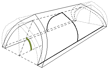
Start Angle |
For an extruded Shell only. Angle of the Shell profile, measured to the Shell’s inclination angle, at the starting end of the extruded Shell. Start angle value is set in the Extrusion Properties panel of Shell Settings or in the Info box. |
|
|
End Angle |
For an extruded Shell only. Angle of the Shell profile, measured to the Shell’s inclination angle, at the second end of the extruded Shell. End angle value is set in the Extrusion Properties panel of Shell Settings or in the Info box. |
|
|
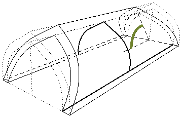
Distortion Angle |
Distortion angle value is set in the Extrusion Properties or Revolution Properties panel of Shell Settings or in the Info box. For an Extruded Shell: Angle of the Shell profile, measured to the Shell plane. By default: 90 degrees, but changing it enables you to extrude the Shell profile at a angle, creating a distorted Shape Shell. For a Revolved Shell: Angle of the axis of the revolved Shell, measured to the Shell plane angle. |
|
|
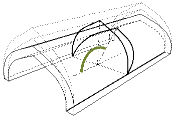
Revolution Angle |
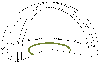
For a Revolved Shell only. Angle by which the Shell is rotated around its axis. Revolution angle value is set graphically, when creating the Shell, or in the Revolution Properties panel of Shell Settings or in the Info box. |
|
|
Trimming Body |
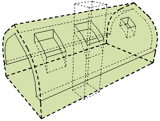
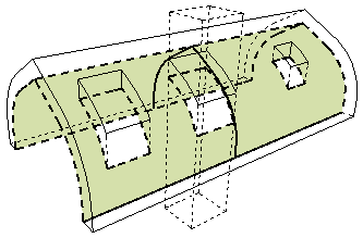
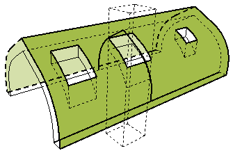
•Editable •Upward Extrusion •Downward Extrusion This value is set in the Model Panel of Shell Settings. Determines the geometry of the Trimming Body which acts upon other elements when they are trimmed by this Shell. |
|
|
Building Material/Composite |
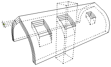
Name of the Building Material or Composite structure assigned to this Shell. |
|
|
Insulation Skin Thickness |
Thickness of the Skin defined as “Shell Insulation Skin type” in Options > Project Preferences > Calculation Units & Rules. |
|
|
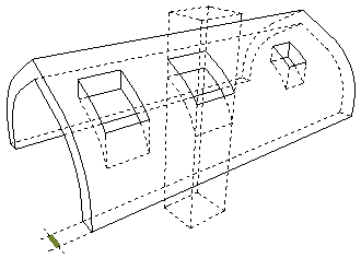
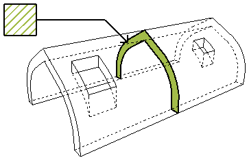
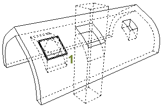
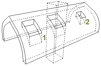
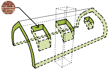
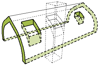
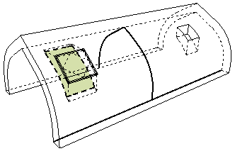
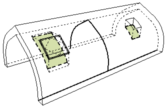
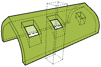
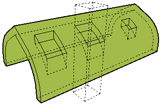
Holes and Skylights Holes include: 1. the holes cut by Skylights, placed into the Shell with the Skylight tool, and 2. the holes added manually to the Shell. “Openings” in Shells can be Skylights only. |
||
|
Number of Skylights |
Number of Skylights placed into the Shell. |
|
|
Number of Holes |
Number of holes created in the Shell manually, plus the number of holes cut by Skylights placed in the Shell |
|
|
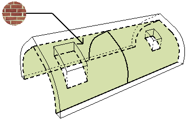
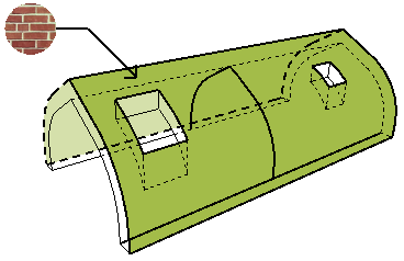
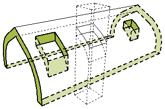
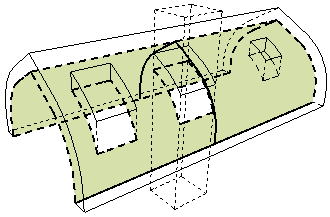
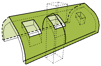
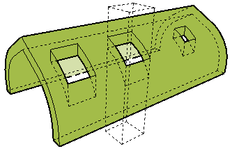
Surface of the Shell on the Reference Side |
Name of the Surface of the Shell as defined in the Model Panel of Shell Settings, in the control for “Surface on the Reference Side.” |
|
|
Surface of the Shell on the Opposite to Reference Side |
Surface of the Shell as defined in the Model Panel of Shell Settings, in the control for “Surface on the Opposite Side.” |
|
|
Edge Surface |
Name of the Surface assigned to the Shell edge, in the Model panel of Shell Settings. Note: Even if the listed Shell edge has a custom surface, the listed surface is the Shell’s edge surface as shown in the Model panel of Shell Settings. |
|
|
Net Surface Area of the Reference Side |
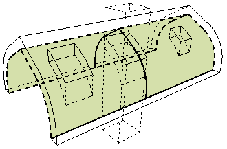
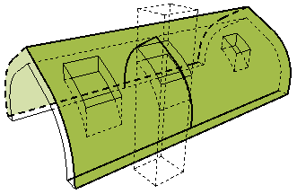
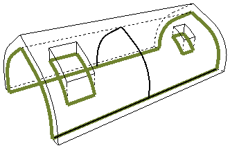
Surface area of the Shell on the Reference Side, reduced by the surface of any holes. Does not take SEO’s into account. (Reference side: where the profile line is drawn.) |
|
|
Net Surface Area of the Opposite to Reference Side |
Surface area of the Shell on the side opposite to the Reference Side, reduced by the surface of any holes and taking trims, Shell contour and SEO’s into account. (Reference side: where the profile line is drawn.) |
|
|
Net surface area of the edges |
Total surface area of all edges of the Shell. |
|
|
Openings Surface Area |
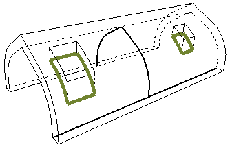
Total surface of all Skylights placed in the Shell. |
|
|
Holes Surface Area |
Total surface of all skylights plus all manually drawn holes in the Shell. |
|
|
Gross Surface Area of the Reference Side |
Surface area of the Shell on the Reference Side, including the surface of any holes. Surface is reduced by any trims and the Shell contour, but does not take SEO’s into account. |
|
|
Gross Surface Area of the Opposite to Reference Side |
Surface area of the Shell opposite to the Reference Side, including the surface of any holes. Surface is reduced by any trims and the Shell contour, but does not take SEO’s into account. |
|
|
Gross Surface Area of the Edges |
Surface area of all edges of the Shell, including the surface of any holes. Surface is reduced by any trims and the Shell contour, but does not take SEO’s into account. |
|
|
Conditional Surface Area of the Reference Side |
Surface area of the Reference side of the Shell, taking trims, Shell contour and SEO’s into account. The value is reduced by the surface of holes only if a hole exceeds a given area, as defined in Options > Project Preferences > Calculation Units & Rules (“Reduce Shell surface by…”) |
|
|
Conditional Surface Area of the Opposite to Reference Side |
Surface area of the Shell opposite to the Reference side, taking trims, Shell contour and SEO’s into account. The value is reduced by the surface of holes only if a hole exceeds a given area, as defined in Options > Project Preferences > Calculation Units & Rules (“Reduce Shell surface by…”) |
|
|
Net Volume |
Volume is reduced by the surface of any holes, and takes trims, Shell contour and SEO’s into account. |
|
|
Conditional Volume |
Conditional Volume takes holes into account only if they exceed the minimum as set in Options > Project Preferences > Calculation Units & Rule. Conditional Volume takes trims, Shell contour and SEO’s into account. |
|
|
Gross Volume |
Volume of the Shell, including the volume of any holes. Volume is reduced by any trims and the Shell contour, but does not take SEO’s into account. |
|
|
Perimeter |
Total perimeter of the 3D contour of the Shell, including the perimeter of any holes. |
|
|
Holes Perimeter |
Total perimeter of all holes in the Shell. |
|

