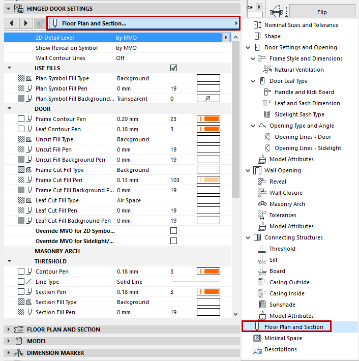
Floor Plan and Section Tab Page (Door/Window Settings)
The following is a description of the Floor Plan and Section tab page of the Custom Settings Panel of Door or Window Settings, from the INT ARCHICAD Library.
This tab page contains all of the 2D display parameters for the various parts of the opening, as defined for this GDL object in its user interface script. The available parameters vary depending on the opening’s components and their geometry.

Note: Alternatively, you can use the 2D attributes on the Floor Plan and Section panel of Door/Window Settings. This method involves a reduced number of parameters for simplicity. See Override GDL Object Attributes of Doors/Windows, below.
While setting the parameters, it is worth displaying the Preview from Door/Window Settings to see how your definitions will affect the display.
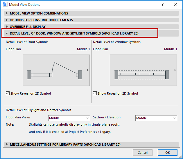
Note that some display parameters are “by MVO”, that is, corresponding to the options set in Model View Options (Document > Model View > Model View Options), but you can override some of these attributes for the particular opening being edited.
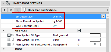
The first three parameters apply to the opening as a whole.
2D Detail Level: Choose a preferred level of detail for the 2D display of the opening.
•if you choose by MVO, the detail level corresponds to the options set in Model View Options (Document > Model View > Model View Options):
•if you choose Scale Sensitive, then the amount of detail shown varies depending on project scale.
Otherwise, you can fix the detail level to a given level (e.g. 1:200), or turn it off (in which case, no 2D symbol is shown at all).
Show Reveal on Symbol: Choose the scale at which the reveal should be displayed on the Floor Plan. (Reveal will not be displayed if the scale is larger than the chosen value.)
Wall Contour Lines: Set the Wall Contour lines for the opening display. If you turn on any of the contour lines, you can set separate line types for hidden/visible lines.
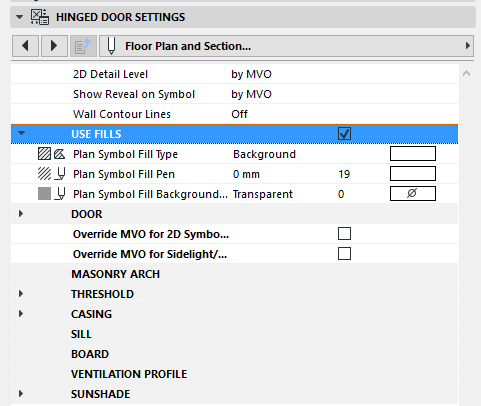
Use Fills on Doors/Windows
To apply any fills to the door/window, check the Use Fills box to enable all fill parameters. If Use Fills is off, the opening display will not use any fills on any of its components.
Override GDL Object Attributes of Doors/Windows
Typically, you will define the 2D attributes (line type, pen, fill) for each component of the Window/Door on the Floor Plan using the Floor Plan and Section tab page of the Custom Settings panel, described above.
However, you may wish to override these, using the simplified settings of the Floor Plan and Section Panel of Door/Window Settings.
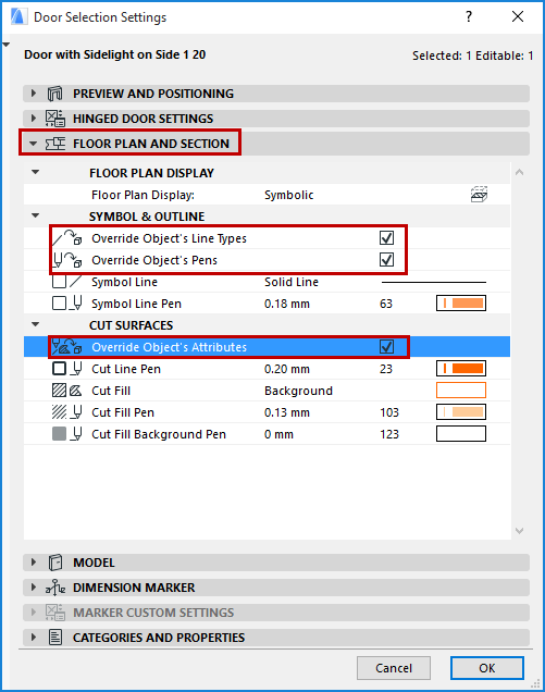
Set the attributes for cut, uncut and overhead lines and pens as needed on the Floor Plan and Section panel of Door/Window Settings (or the Info Box).
For these settings to take effect, make sure that the applicable Override Object’s /Line Types/Pens/Attributes checkbox(es) are on. Otherwise, the Door/Window will be displayed with its GDL Object attributes.
Note: For some doors/windows, no relevant GDL parameter is defined. In this case, the object will be displayed using the attributes defined in the Floor Plan and Section panel (regardless of the Override checkboxes).