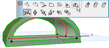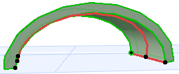
Options for Editing Extruded Shells
About the Extrusion Vector
•One end of the extrusion vector (its initially placed point) is distinguished by a larger hotspot; this represents the Shell’s base height.
•The extrusion vector can be located apart from the Shell body itself.

Edit Extrusion Vector
Click on either end of extrusion vector to bring up these commands on the pet palette.
•Edit Extrusion Length: Edit the length of the extrusion vector. Its slant and its other geometric parameters remain unchanged.
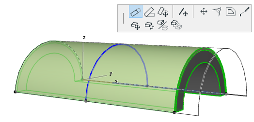
•Edit Extrusion Slant: Edit the slant of the extrusion vector. The extrusion length, as well as the Shell starting/ending angles and the distortion angle, remains unchanged.

•Stretch: Edit the length of the extrusion vector and its rotation. You can also rotate its slant, if you join the vector endpoint to an existing element. The starting/ending angles and the distortion angle remain unchanged.
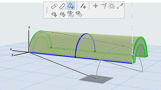
If you stretch the Shell to reach a point on another existing element, the Shell slant changes accordingly:
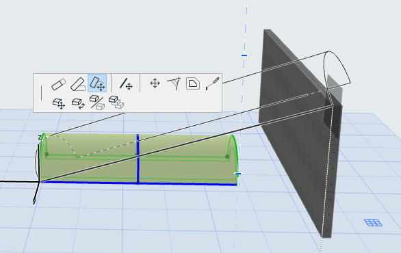
•Drag Extrusion Vector: Drag the Shell’s extrusion vector to another location. Click anywhere on the Extrusion vector to bring up this command from the pet palette.
If you drag the extrusion vector, two things happen:
•The Shell’s base elevation changes to the new location of the vector
•The Shell’s start and end angles are now editable based on this new vector location. (The vector serves as the axis of rotation for the Shell start/end angles.)

Edit Profile of Extruded Shell
Select the Shell and use the familiar pet palette commands to edit the profile. Note that even if you move the profile, the extrusion vector remains in place.
•Drag, Rotate, Mirror Profile
These three commands operate on the Shell profile on its own plane (the plane is displayed in the 3D window while you edit):


•Insert New Node
•Curve Edge


•Set Distortion Angle
Select the Shell profile and use the pet palette command to set the distortion angle graphically. This can be useful, for example, to “flatten” your vault-shaped Shell into more elliptical form.


View the resulting distortion angle in the Tracker, the Info Box or Shell Settings.
•Continue Profile
If you select the endpoint of the Shell Profile, the Continue Profile command is available in the pet palette. Use this add one or more segments to the profile, as if you were extending a polyline (double-click to complete the polyline, or click on the other profile endpoint to create a closed profile.)


Remove profile Edge: For a closed Shell Profile, the Remove edge command is available in the pet palette from any selected profile edge. Click to remove that segment.
