
Create Curtain Wall in the 3D Window
Input the Curtain Wall using the usual methods for a construction tool.
Note: If your Scheme has a fixed-size grid pattern, the ghost feedback and pencil/snap point indicate where the next pattern segment will be complete.


In the 3D window, the default Curtain Wall input plane is the same as the current 3D input plane.
To define other input planes, see Curtain Wall Input Plane in 3D Window.
Polyline Method
1.With the Curtain Wall tool active, choose the Polyline - Single geometry method and the Default Input Plane from the Info Box.

2.Click to begin drawing the Curtain Wall Reference Line.
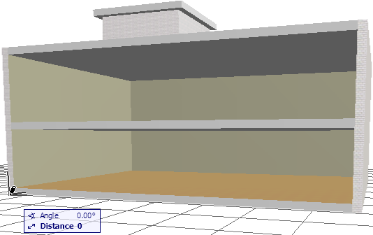
In our example:

3.Click at the two front corners of the building to define the Reference Line length.
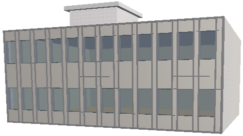
View the result.

Boundary Method
1.With the Curtain Wall tool active, choose the Boundary geometry method and the Intelligent Input Plane Method from the Info Box.

2.Define the Input Plane by a series of clicks.
3.Begin drawing the desired Curtain Wall Boundary on the input plane, clicking at each node as when drawing any polyline.
Note: The Reference Line of this Curtain Wall is the first Boundary segment you draw.
4.Double-click or click with the Hammer cursor to close the polygon.
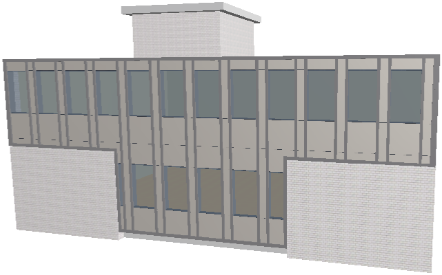
View the result.

Related Topics: