Winder Types for Equal-Going Winders
Equal Goings means that all goings in the Stair are equal, both on the straight and the winding steps.
In Stair Settings-Geometry and Positioning Panel:
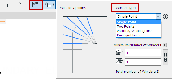
Choose one of four types of Equal-Going Winders from the pop-up: Single Point, Two Points, Principal Lines, and Auxiliary Walking Line.

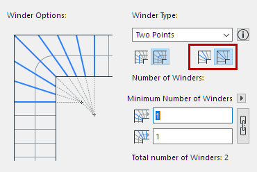
As applicable, choose either Riser or Tread in the Middle for your winding type:

Winder with Equal Goings: Construct with Riser or Tread in the Middle
All except the Single Point method have two versions, depending on whether the center of the Winder is a Riser or a Tread.
|
Single Point Method |
Two Points Method |
|
|
|
Riser in the Middle |
Tread in the Middle |
|
Principal Lines Method |
Auxiliary Walking Lines Method |
||
|
Riser in the Middle |
Tread in the Middle |
Riser in the Middle |
Tread in the Middle |
Each method is described below:
Two Points Method - Riser in the Middle
Two Points Method - Tread in the Middle
Principal Lines Method - Riser in the Middle
Principal Lines Method - Tread in the Middle
Auxiliary Walking Line Method - Riser in the Middle
Auxiliary Walking Line Method - Tread in the Middle
1.Equal goings are measured along the walking line, starting from the bottom of the stair. The going closest to the turning point is considered the Center Tread of the Winder.
2.Start and End lines of the Winder – aka the last and first straight step – are constructed, based on the Number of Winding Steps parameter.
3.Start and End lines are extended, their intersection point forms the centerpoint of the Winder.
4.The equal going points measured along the walking line are connected to the centerpoint, these lines form the risers of the winding steps.

Two Points Method - Riser in the Middle

1.Center of the Winder is constructed:
–A single Riser is constructed in the bisector of the turning.
2.Equal goings are measured along the walking line, in both directions, starting from the point where the bisector intersects the walking line.
3.Start and End lines of the Winder – aka the last and first straight step – are constructed, based on the Number of Winding Steps parameter.
4.Start and End lines are extended, their intersection points with the bisector form the two centerpoints of the Winder.
5.The equal going points measured along the walking line are connected to corresponding one of the two centerpoints. These lines form the risers of the winding steps.
Two Points Method - Tread in the Middle

1.Center of the Winder is constructed:
–A single Going is measured along the walking line, symmetrical to the bisector of the turning.
–The Tapered Tread Minimum Width value is measured on the inner edge of the turning, symmetrical to the bisector.
–The points on the inner edge and the points on the walking line define the Center Tread.
2.Equal goings are measured along the walking line, starting from the point where the edges of the Center Tread intersect walking line.
3.Start and End lines of the Winder – aka the last and first straight step – are constructed, based on the Number of Winding Steps parameter.
4.Start and End lines are extended. Edges of the Center Tread are also extended. The intersection points of these lines form the two centerpoints of the Winder.
5.The equal going points measured along the walking line are connected to corresponding one of the two centerpoints. These lines form the risers of the winding steps.
Principal Lines Method - Riser in the Middle

1.Center of the Winder is constructed:
–A single Riser is constructed in the bisector of the turning.
–Equal goings are measured along the walking line, in both directions, starting from the point where the bisector intersects the walking line.
–The Tapered Tread Minimum Width value is measured on the inner edge of the turning, in both directions.
–The points on the inner edge and the points on the walking line define the two Center Treads.
2.Equal goings are measured along the walking line, in both directions, starting from the Center Treads.
3.Start and End lines of the Winder – aka the last and first straight step – are constructed, based on the Number of Winding Steps parameter.
4.Start and End lines (the Principal Lines) are extended. Edges of the two Center Treads are also extended.
5.The points where the First Center Tread Edge and the Bisector intersect the Start line define the distance X.
6.Distance X is measured multiple times along the Start line. These points are connected to the respective equal going points measured along the walking line. These lines form the risers of the starting half of the winder.
7.The points where the Last Center Tread Edge and the Bisector intersect the End line define the distance Y.
8.Distance Y is measured multiple times along the End line. These points are connected to the respective equal going points measured along the walking line. These lines form the risers of the ending half of the winder.
Principal Lines Method - Tread in the Middle

1.Center of the Winder is constructed:
–A single Going is measured along the walking line, symmetrical to the bisector of the turning.
–The Tapered Tread Minimum Width value is measured on the inner edge of the turning, symmetrical to the bisector.
–The points on the inner edge and the points on the walking line define the Center Tread.
2.Equal goings are measured along the walking line, in both directions, starting from the Center Tread.
3.Start and End lines of the Winder – aka the last and first straight step – are constructed, based on the Number of Winding Steps parameter.
4.Start and End lines (the Principal Lines) are extended. Edges of the Center Tread are also extended.
5.The points where the Center Tread Edges intersect the Start line define the distance X.
6.Distance X is measured multiple times along the Start line. These points are connected to the respective equal going points measured along the walking line. These lines form the risers of the starting half of the winder.
7.The points where the Center Tread Edges intersect the End line define the distance Y.
8.Distance Y is measured multiple times along the End line. These points are connected to the respective equal going points measured along the walking line. These lines form the risers of the ending half of the winder.
Auxiliary Walking Line Method - Riser in the Middle

1.Center of the Winder is constructed:
–A single Riser is constructed in the bisector of the turning.
–Equal goings are measured along the walking line, in both directions, starting from the point where the bisector intersects the walking line.
–The Auxiliary Walking Line is constructed, by offsetting the Walking Line to 200mm from the inner edge.
–2/3 of the Going is measured along the Auxiliary Walking Line, in both directions.
–The points on the walking line and the points on the Auxiliary Walking Line define two Center Treads.
2.Equal goings are measured along the walking line, in both directions, starting from the Center Treads.
3.Start and End lines of the Winder – aka the last and first straight step – are constructed, based on the Number of Winding Steps parameter.
4.Start and End lines (the Principal Lines) are extended. Edges of the two Center Treads are also extended.
5.Going length is measured multiple times along the Start line, starting from the point where the First Center Tread Edge intersects the Start Line.
6.These points are connected to the respective equal going points measured along the walking line. These lines form the risers of the starting half of the winder.
7.Going length is measured multiple times along the End line, starting from the point where the Last Center Tread Edge intersects the End Line.
8.These points are connected to the respective equal going points measured along the walking line. These lines form the risers of the ending half of the winder.
Auxiliary Walking Line Method - Tread in the Middle

1.Center of the Winder is constructed:
–A single Going is measured along the walking line, symmetrical to the bisector of the turning.
–The Auxiliary Walking Line is constructed, by offsetting the Walking Line to 200mm from the inner edge.
–1/2 of the Going is measured along the Auxiliary Walking Line, symmetrical to the bisector of the turning.
–The points on the walking line and the points on the Auxiliary Walking Line define the Center Tread.
2.Equal goings are measured along the walking line, in both directions, starting from Center Tread.
3.Start and End lines of the Winder – aka the last and first straight step – are constructed, based on the Number of Winding Steps parameter.
4.Start and End lines (the Principal Lines) are extended. Edges of the Center Tread are also extended.
5.Going length is measured multiple times along the Start line, starting from the point where the First Center Tread Edge intersects the Start Line.
6.These points are connected to the respective equal going points measured along the walking line. These lines form the risers of the starting half of the winder.
7.Going length is measured multiple times along the End line, starting from the point where the Last Center Tread Edge intersects the End Line.
8.These points are connected to the respective equal going points measured along the walking line. These lines form the risers of the ending half of the winder.
Winder Segments
In case of a Winder Segment, the midpoint of the Winder part of the walking line is considered the starting point of the Winder.
•Bisectors are constructed as the perpendicular to the walking line through this point.
•Equal Goings are measured starting from this point.
•Tapered Tread Minimum Widths are measured starting from this point’s projection onto the inner edge.