
Each Wall has a reference line and a direction. The Wall reference line is visible on the Floor Plan if you switch on:
View > On-Screen View Options > Walls & Beams Reference Lines

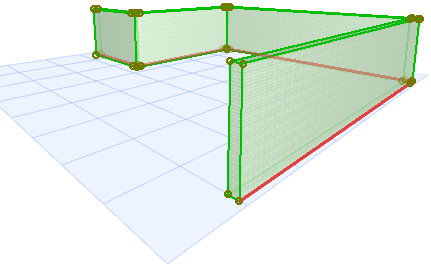
In the 3D window, the reference line of a selected Wall is shown in a separate color: you can change this color using the “Reference Lines in 3D” setting at Options > Work Environment > Selection and Element Information.
Change Wall Reference Line Position
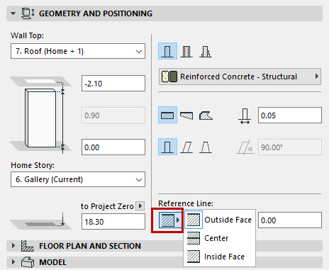
Use the Info Box or Geometry and Positioning Panel of Wall Settings to choose a reference line position. Click the “C” shortcut to cycle through the reference plane options in the Wall Info Box.
Reference Line of a Basic Wall
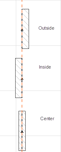
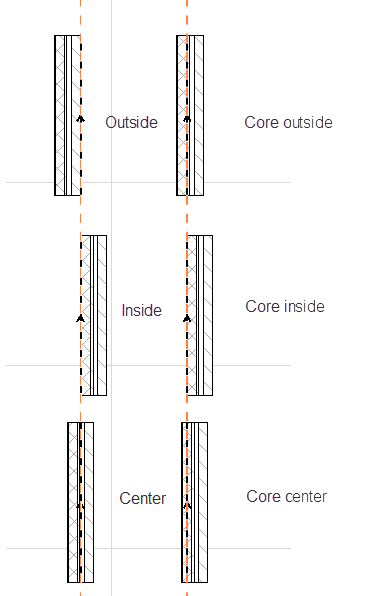
A basic Wall has three possible reference lines: running along the outside face, inside face, or the center.
By default, the reference line runs along the “outside face”.
Reference Line of a Composite Wall
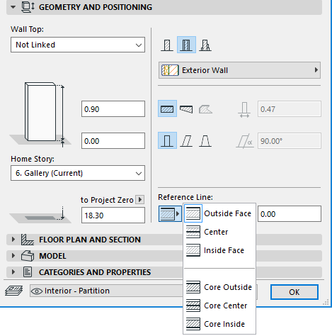
A composite Wall has six possible reference lines: outside/inside/center of the Wall, plus outside/inside/center of the Wall core.
Note: If the chosen composite structure has no core, then the core-related Reference Line choices are grayed out.
By default, the reference line runs along the “outside face”.
For a composite, the “outside” surface is the first listed skin of the composite, in Composite Settings.
Reference Line of a Trapezoid Wall
A Trapezoid wall has two possible reference line locations: Outside Face or Core Outside (if it has a core).
See also Create a Trapezoid Wall.
Reference Line of a Polygon Wall
Reference line controls in Wall Settings do not apply to Polygon walls. (Polygon wall reference lines can be moved graphically via the pet palette.)
Reference Line of a Profile (Complex) Wall
The reference line of a Profile (complex) wall depends on the user origin defined in Profile Manager/Editor.
Reference Line Offset: If using an “outside” or “inside” reference line, enter a positive offset to move the reference line toward the center (or center of core) of the Wall. A negative offset will move the reference line away from the center (or core center). (No offset is available if the reference line is in the center.)
As you adjust the reference line location, notice that the body of the Wall moves laterally. The reference line stays in place.
Note: In contrast, to move the reference line while retaining the Wall’s position intact, and/or mirror the openings, use the Modify Wall Reference Line command.
See Modify Wall Reference Line.
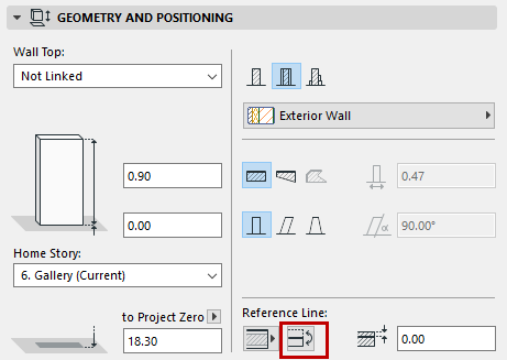
Flip Wall Along Reference Line
This command flips (or mirrors) a selected Wall along its reference line. The reference line stays in place, but the body of the Wall flips to the other side. Notice that the openings do not change their opening direction.
The command is available in the Wall Info Box, and in the Geometry and Positioning Panel of Wall Settings.

Note: To move the reference line while retaining the Wall’s position intact, and/or mirror the openings, use the Modify Wall Reference Line command.
See Modify Wall Reference Line.
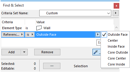
Reference Line in Interactive Schedule/Find & Select
In the Interactive Schedule, you can Find & Select the Walls in your project, or list them in the Interactive Schedule, based on the location of their reference lines:

•The reference line helps you achieve the precise connection of Walls for clean intersections. Associating the reference line to the core allows finishes to be edited without moving the core’s position.
•The reference line establishes hotspots and edges for selecting, moving and transforming Walls. Some Pet Palette editing commands are accessible only by clicking on the reference line of the selected Wall, as shown in the two images here:


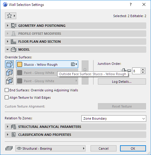
•The reference line position determines the Wall’s “outside” and “inside” surfaces. (The reference line is on the outside of the Wall.) Separate surface materials can be applied to the Wall’s “outside” and “inside” surfaces, using the controls in the Model Panel of Wall Settings.
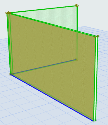
Wall Direction
The direction of the Wall, indicated by the arrow on the reference line, is defined by the order in which you define the wall’s endpoints.
Note: The directions of curved Walls and polygon Walls are fixed and cannot be reversed.
Note: With the commands at Edit > Reference Line and Plane, you can modify the Reference Line position and the direction of selected Wall type elements.