Calculation of Projected Component/Skin Area
Use the Projected Component/Skin Area field to calculate the area of any components of basic, composite or profiled elements.
Note: Morphs and basic non-veneer columns are an exception: skin area cannot be calculated for these elements.
Both Skin/Component Volume and Area are available as GDL Requests for use in listing and property objects. Skin/Component Volume and Area, however, cannot be displayed as parameters in placeable elements such as Labels.
Related Topics:
Projected Skin Areas of Basic and Composite Elements
Component Areas of Complex Profiles
Projected Skin Areas of Basic and Composite Elements
For most elements, the calculated area is that of the projection onto the virtual plane that runs through the center of the skin/component.
Watch the Video
Watch the Video
The following table gives more details about area calculation for each element type.
|
Basic or Composite Element
|
Which Plane is used to Calculate Projected Component/
Skin Area?
|
|
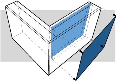
Regular Straight Wall
|
The vertical plane that runs through the center of the skin.
|
|
|
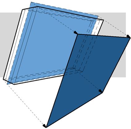
Slanted Wall
|
The slanted plane that runs through the center of the skin.
|
|
|
Curved Wall
|
The plane of the vertical cylinder that runs through the center of the skin.
|

|
|
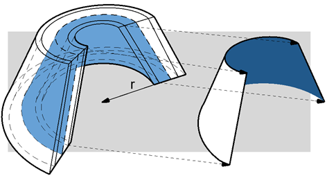
Curved Slanted Wall
|
The plane of the cone that runs through the center of the skin.
|
|
|
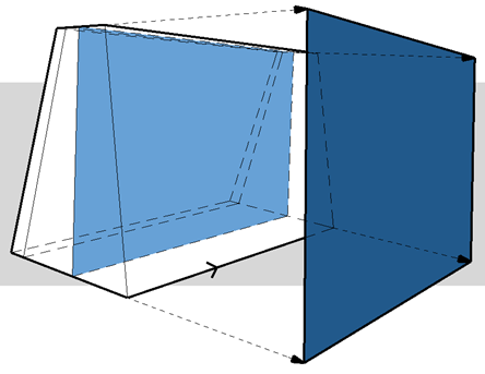
Double Slanted Wall
|
The plane of the variable-thickness skin that is closest to the wall's reference line.
|
|
|
Trapezoid Wall
|
The plane of the variable-thickness skin that is closest to the wall's reference line.
|

|
|
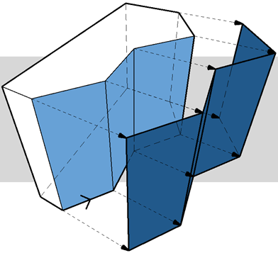
Polygon Wall
|
The plane(s) of the vertical polygon(s) defined by the reference edge(s).
|
|
|
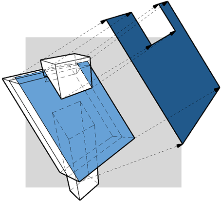
Roof
|
Plane of the roof.
|
|
|
Slab
|
Plane of the slab.
|

|
|
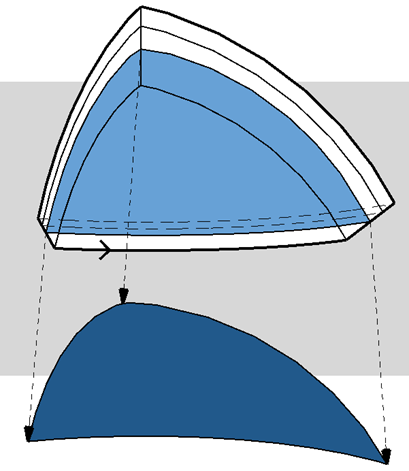
Shell
|
The plane of the skin that is closer to the Shell reference plane
|
|
|
Mesh
|
The Mesh reference plane
|

|
|
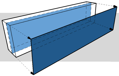
Straight Beam
|
The Beam's vertical plane
|
|
|
Column without Veneer
|
No skin/component area is calculated.
|
|
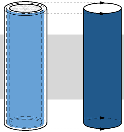
Column with Veneer (circular)
|
Circular column with veneer: The plane of the centerline of the veneer component.
|
|
|
Column with Veneer (rectangular)
|
The program calculates the veneer as if it were divided into four parts as shown, and the vertical plane of each is used.
|

|
|
Morph
|
No skin/component area is calculated
|
Component Areas of Complex Profiles
For complex profiles, the projected area of each component skin can be calculated.

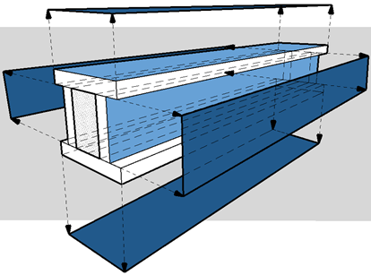
When listing these areas for a profile element, you can control:
•which components should be included in listing the projected component areas
•for each component, which plane should be used as the basis for area calculation
These features are described below.
Choose Profile Components for Area Listing
1.In the Profile Editor window, select a component.
2.In the Profile Manager (Options > Complex Profiles > Profile Manager), activate the List Component Area checkbox for each component whose area you want to list.
In this example, we are editing the Brick Wall w Footing element. The veneer's checkbox is on, and its area will be included in the schedule. The footing area, however, is not relevant and its checkbox is off.
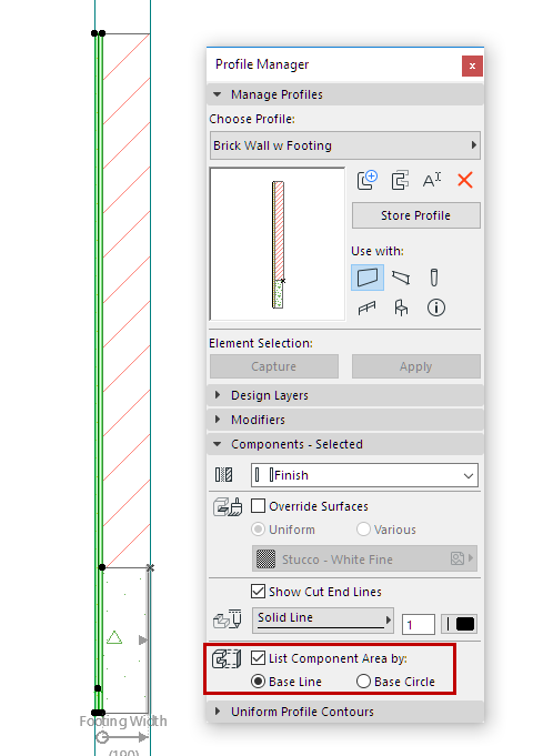

List Component Area: On for Veneer, Off for Footing
3.Click Store Profile to save changes.
4.The area of the concrete footing component is not included in the schedule.

Adjust Calculated Area of Profile Components
To adjust how the component's projected area is calculated, you can graphically edit its Base Line or Base Circle in the Profile Editor, if needed.
•Use the Base Line to calculate the component area as projected onto the flat surface represented by the line. By default, the base line is located along the longest segment of the profile.

•Use the Base Circle to calculate the area as projected onto an arched component.
Note: To keep all the Base Lines visible in Profile Editor, regardless of component selection, make sure you have turned on View > On-Screen View Options > Component Area Base Line/Circle.
In this example, you need the area of the Generic Column on its horizontal surface.
1.In Profile Editor, select the component.
2.Activate the List Component Area checkbox.
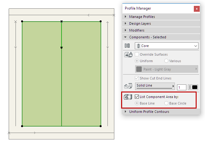
3.The component's base line is vertical, which is not the area you need. In the Profile Editor window, select the base line and rotate it to a horizontal position.


4.Click Store Profile to save changes.
5.The horizontal area of the column is included in the schedule.
For general information on editing in the Profile Manager, see Profile Manager.


