Vary Elevations During Routing
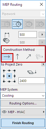
All Routing operations begin with the Constant Elevation setting (the default Construction Method shown in the Routing palette).

Once you start Routing, you can choose alternative Construction Methods:
(Can also be set in the Tracker, during Routing.)
•Vertical Rise: Switch the construction method to “Vertical Rise”.
–In the Floor Plan, a dialog box appears: enter the elevation at which the next element should end. Click OK to close the dialog box and place the vertical segment, and continue routing.
–In the 3D window, just draw the segment along the vertical editing plane.
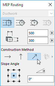
•Constant Slope Angle: Switch the construction method to “Constant Slope Angle” and enter an angle. Subsequent elements of the current Routing will be placed along this slope until you change the angle value or switch to a different method.

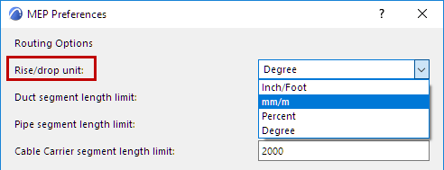
Note: The angle unit (such as degree or mm/meter) of the slope is defined in the MEP Preferences: Rise/Drop Unit control.

Use 3D Editing Planes During Routing
In the 3D window:
Begin Routing and place at least one element using any of the construction methods described above.
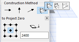
Then switch to one of the following construction methods (click one of the three fly-out options of the 3D Editing Planes icon) to constrain the Routing along to a 3D plane:

•Width Plane: Routing will continue along the width plane: the plane created where the reference line intersects with the “width” direction of the last placed routed element.
•Height Plane: Routing will continue along the height plane: the plane created where the reference line intersects with the “height” direction of the last placed routed element.
•Perpendicular Plane: Routing will continue along the plane perpendicular to the vector of the last placed element.