For general information, see Master Layouts.
This dialog is available from
•Context menu of Layout or Master Layout
•In Navigator: Select Master Layout, then click Settings
•Document > Layout Book > Master Layout Settings

Note: Length units defined for the Master Layout are Layout units, defined in Options > Project Preferences > Working Units.)
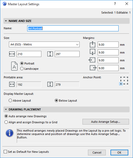
•Name: Enter a Name for the Master Layout in the text field.
•Size: Define the Master Layout size using the standard paper sizes listed in the drop-down list, or the Custom option. The two fields below give you feedback on the horizontal and vertical dimensions of the Layout.
•Margins: Enter values for the Master layout’s four margins in the text fields.
•Choose Portrait or Landscape as the Master Layout’s orientation.
Printable area: This area gives you feedback on the Master Layout’s printable area (taking its Size and Margins into consideration).
Anchor Point: Click one of the nine points to use as an anchor for your master layout.
Display Master Layout
•Above Layout: Master Layout items will be placed on top of the Layout (in some cases, obscuring some of the Layout content).
•Below Layout: Master Layout items will be displayed behind the Layout. Contents of the Layout may obscure some Master Layout items.
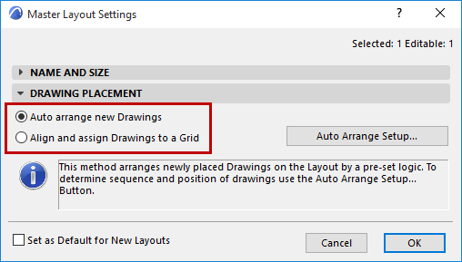
Choose one of the two logics for placing multiple drawings on the layout.
Note: The default logic is “Auto Arrange.” If you are placing only a single drawing on the Layout, it will be placed in the center of the Layout.

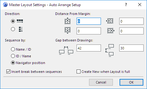
If you choose this option, click Auto Arrange Setup to set the following:

Direction: Choose either horizontal or vertical to determine the direction in which subsequent drawings are placed on the Layout.
Distance from Margin: For each of the four sides of the Layout, define a margin of space.
Sequence by: When placing multiple drawings at once, the Sequence setting determines the order in which they appear on the Layout.
•Name/ID: Alphabetical by name; in case of identical names, drawings are placed in order of ID (numerical or alphabetical).
•ID/Name: In ID order; in case of identical IDs, drawings are placed according to their name (alphabetical order).
•Navigator position: Drawings are placed in the order (top to bottom) that they are listed in the Navigator View Map. (Floor Plans are an exception; they are placed according to their View Map order from the bottom up, e.g. Story 1, 2, 3...).
Insert break between sequences: “Sequence” depends on your choice in the Sequence by options above:
•if you are sequencing by Name/ID (or ID/Name): Check this box to start a new row/column every time the Name (or ID) changes.
•If you are sequencing by Navigator position: Check this box to start a new row/column for each new folder in the Navigator View Map. For example, Drawings from the Details folder will be placed in one row, from the Sections folder in the next, etc.
Gap Between Drawings: Define the length of the gaps between the rows and columns of placed drawings. (Length units here are Layout units, defined in Options > Project Preferences > Working Units.)
Create New when Layout is Full: Create a new Layout if the current layout is full.
Align and Assign Drawings to a Grid
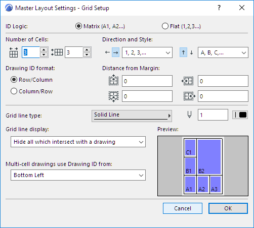
If you choose this option, click Grid Setup to access the grid settings options. As you set these options, consult the Preview picture.

ID Logic: Assign an ID to each grid cell by a defined logic:
•Matrix: Each cell ID is based on its column and row number
•Flat: Cell IDs are numbered in sequence.
Number of Cells: Define number of columns and rows in your Grid.
Depending on which ID assignment logic you choose (Matrix or Flat), the subsequent controls will vary.
Matrix-Style ID Options
Direction and Style
•Choose how to assign IDs to grid columns/rows (left/right, and up/down)
•Choose an ID numbering style
Drawing ID Format: For Matrix-style IDs, define numbering format:
•Row, then Column, or
•Column, then Row
Flat-Style ID Options
Start From: Define one corner of the grid as the starting point for assigning cell IDs
Style: Choose an ID numbering style
Primary Direction: Define the direction (horizontal or vertical) in which to assign the cell IDs, starting from the corner you designated (Start From).
The rest of the controls in the panel apply to the Grid regardless of ID logic.
Grid Line Display Options
Note: These Grid line display settings also affect printed output.
•Distance from Margin: Define the distance of the Grid from the paper margin (top, bottom, left and right).
•Choose line type and pen color
•Show/Hide All Grid Lines
•Hide all which intersect with a drawing: Check this option to hide such grid lines.
Multi-Cell Drawings
Define which cell ID should be assigned as the drawing ID (You will choose one of the drawing’s four corners; the ID of the cell which that corner occupies becomes the drawing ID.)
Set as Default for New Layouts
Check this box if you want this Master Layout to serve as the default Master Layout for new Layouts.