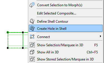
On the Floor Plan or Section window:
1.Select any Shell on the Floor Plan or Section.
2.From the context menu, choose Create Hole in Shell.

3.Draw the desired polygon onto the Shell. (The opening’s plane is the Floor Plan, but you can edit this later.)
See Edit Shell Hole.
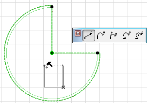
4.View the result in 3D:
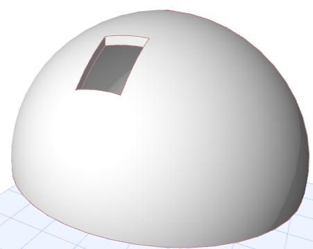
In the 3D Window:
1.Select the Shell.
2.From the context menu, choose Create Hole in Shell.
3.Choose an input plane on which you want to draw the hole: use the feedback to choose the desired plane location. (Choose a plane anywhere in the model; it does not have to be on top of the Shell.)
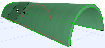
4.Draw the desired polygon onto the input plane. You can edit this later.
See Edit Shell Hole.
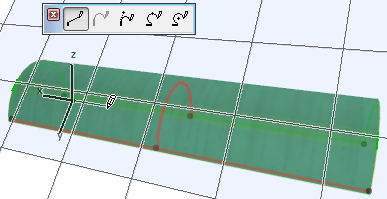
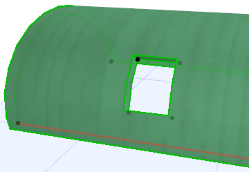
5.View the result.
Listing Shell Holes in the Interactive Schedule
Properties of Shell Holes (e.g. Holes Surface and Perimeter) can be listed in an Interactive Schedule. As with other elements, you can set a preference (“Calculation Rules”) for the size of holes which should be taken into account when calculating Shell volume or surface.
For details, see Conditional Parameter Setup Rules.