To lay out a complete orthogonal or curved grid mesh, use the Grid System function. The Grid System command can save you a lots of time by automating the task of placing multiple Grid Elements in one step, following a defined scheme, and even placing elements on dedicated positions. You can also place dimensions throughout the Grid system in one step.
A Grid System is a collection of Grid Elements; each Grid element continues to act as a distinct element, even though they are placed as part of a system.
Select Design > Grid System. Adjust the settings.
See Grid System Settings.
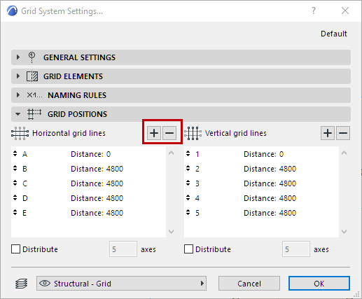
The number of horizontal and vertical grid lines to be placed in this Grid System depends on what you set in the Grid Positions panel: click the plus and minus signs to add or remove individual Grid lines from the Grid System.

The number of Grid lines is shown in the “axes” field below.
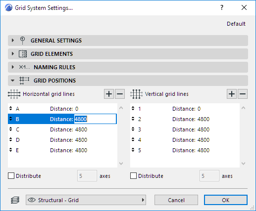
Click in the Distance field of any Grid line to define its distance from the previous Grid line:
If you do not know the distance you will need between your Grid lines, check the Distribute box for either or both Grid line directions (i.e. horizontal and/or vertical grid lines). This will enable you, when you place the Grid system, to set the beginning and endpoints of the Grid system in the given direction, divided into the number of Grid lines defined in the list.
When you are satisfied with Grid System Settings, click OK.
You will see a ghost grid system at the cursor, which you can place with two to four clicks:
•the first click defines the location of the anchor point you selected in the settings
•the second click defines the rotation of the grid system
•if you selected the Distribute function as well, then one or two additional clicks are required to define the full distances for distribution in one or both directions, depending whether you checked Distribute for one or both directions.
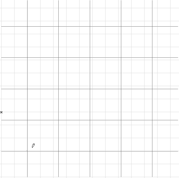
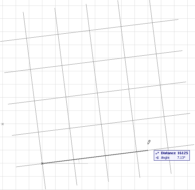
Note: You can select and edit all or selected elements of a placed grid system by selecting them using any of the Archicad selection methods.
Place Object, Column or Beams with Grid System
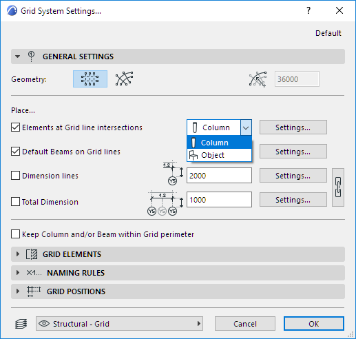
Use the General Settings panel of Grid System Settings to place an Object or Column automatically at every Grid intersection point; and/or to place a Beam along every Grid line of the Grid System.
Note: If you are placing a curved grid system, you have the additional option to place either straight or curved beams along the gridlines.
The Settings button next to each checkbox will take you to the relevant Tool Settings dialog box (Column, Object, Beam).
For details on these controls, see Grid System General Settings Panel.
Although these checkboxes mean that Beams, Columns or objects are placed at each Grid intersection, these elements are independent of the Grid and will not be moved or rotated along with the Grid System.
Dimension Grid System
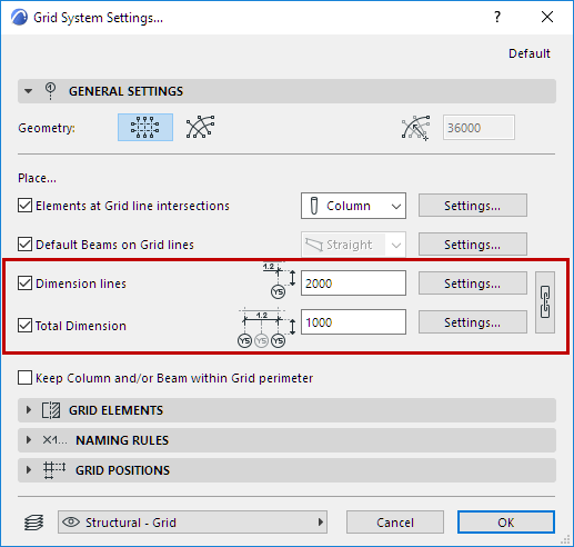
Two additional checkboxes in the General Settings panel of Grid System Settings enable you to automatically dimension each Grid line segment in the system, and/or to place a single total dimension for each Grid line.
These dimensions are associated to the Grid system.
The Settings button to the right of the Dimension checkboxes take you to Dimension Default Settings, where you can set the options for the chosen Dimension type for your Grid System. For example, you can set all of the individual Grid line dimension text to be displayed in italic, while the Total Dimension values are displayed in bold type.
Note that if you would like to use uniform Dimension settings for both dimension lines, then you can use the Chain button to link them together, in the General Settings panel of Grid System Settings.
