Filter and Cut Elements in 3D Dialog Box

Access this dialog box from:
•View > Elements in 3D View > Filter and Cut Elements in 3D
•View Settings (3D Only panel)
•3D Visualization toolbar’s button to open this dialog box.

•3D Document Settings to redefine filtering criteria for a 3D Document.
Note: You may wish to display 3D Zones as solid bodies in shading mode, and all other elements types in wireframe mode. To achieve this effect (a default setting in earlier Archicad versions), apply the predefined “Show 3D Zones as Solid” Layer Combination.
See 3D Document Settings.
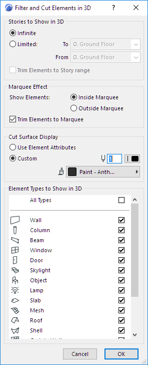
Stories to Show in 3D: Define the stories of the project to be displayed in the 3D window:
•Infinite: Show all elements.
•Limited: Specify a continuous range of stories (from/to stories).
• Trim Elements to Story range: Check this box to clip the model at the story range boundaries. If this box is not checked, then any element that falls at least partially inside the story range will be displayed.
Marquee Effect: If you have used the Marquee tool to create a selection area prior to generating the model, use these options to define which part of the project will be shown in the 3D window:
•Inside Marquee: Elements inside the Marquee will be displayed.
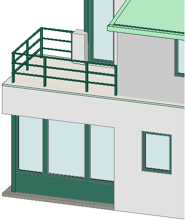
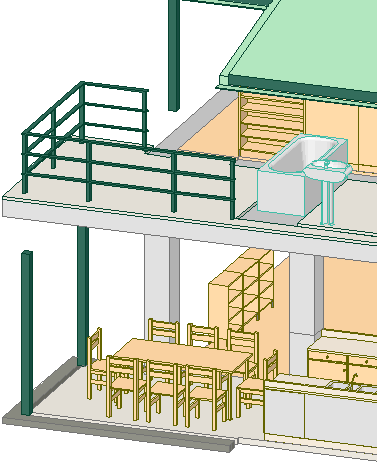
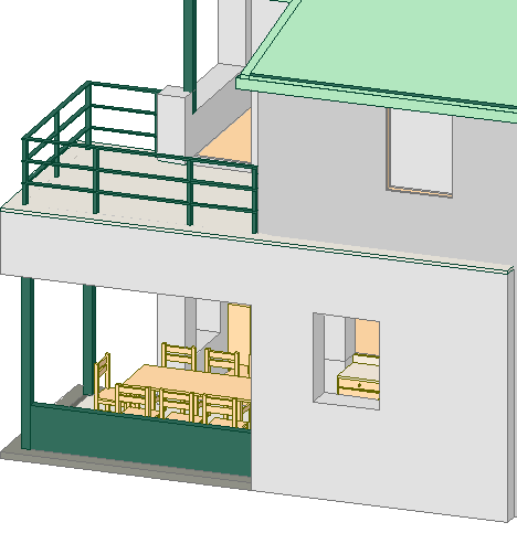
•Outside Marquee: Elements outside the Marquee will be displayed. This option allows you, for example, to exclude internal elements of a house when you need only external views of the 3D model. The Marquee can affect multiple stories, not just the current story.
If there is a Marquee selection made in the Floor Plan, the settings of the Filter Elements in 3D dialog box are observed, but the caption of the 3D window includes the Marquee mention and the range of included stories.
Cut Surface Display: Use these controls to define the surface and pens for the interior surfaces and edges of 3D Cutaways.
•Use Element Attributes: Click this button to use existing Surfaces & Pencolors/Penweights for highlighting the edges and surfaces of elements cut in 3D Sections. The cut surfaces of construction elements will have the same colors/surfaces as the uncut edges (as defined in their respective settings dialog boxes).
•Custom: Click this button to choose Custom Surface & Pencolor/Penweight for highlighting the edges and surfaces of elements cut in 3D Sections.
Surface pop-up palette: Click this pop-up palette to select a custom Surface for exposed interior surfaces of solid elements.
Cut surfaces of Library Parts will be painted according to the surface set for the Library Part. If the Library Part has internal surface descriptions, the first one in the script will define the surface for cut surfaces. The 3D Cutting Planes feature does not show the various layers of composite elements. To obtain sections showing these (if required for working drawings) use the Section/Elevation/IE tools.
The Element Types to Show in 3D checkboxes allow you to turn the 3D Window display of construction elements on and off. With Doors and Windows switched off, openings are interpreted as empty holes. Checking the All Types box selects all element types.


