The Grid Tool allows you to place Grid elements individually or in a Grid System; it is a tool in the Archicad Toolbox.

Grid elements are part of the model and serve as an editable framework for placing multiple elements or for identifying locations in the model.
The Grid Tool creates a custom local structural grid. (In contrast, the Construction and Snap Grid set in the View > Grid Options > Grids and Background is a global, equally distributed net covering the whole 2D window, and is used as an input and editing aid.)
The grid created by this tool is interactive, so you can edit grid elements even after placing them. Grid elements can be edited using Grid Settings.
See Grid Tool Settings.
Grid elements can be placed in either the Floor Plan or the 3D window, but they can be displayed in Sections, Elevations, Interior Elevations and the 3D Document as well.
A Grid element marks a vertical location in the model. Like other model elements, Grid elements are saved along with views.

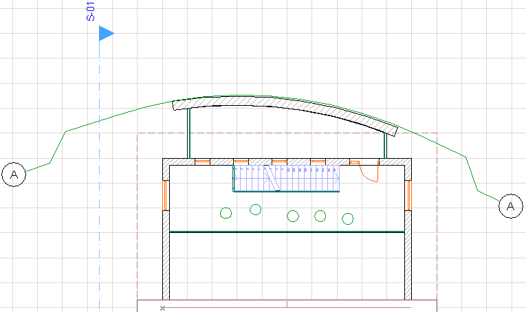
Grid element on the Floor Plan

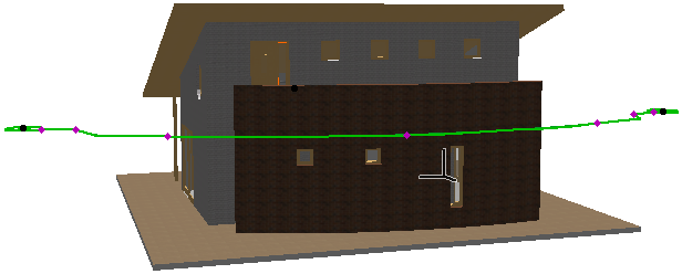
Grid element in the 3D window
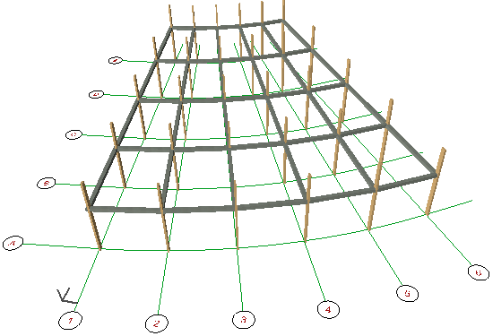
To place a whole scheme of horizontal and vertical gridlines in one step, use the Design > Grid System command. The follow-up Grid System Settings dialog allows you to configure the system of Grid Elements and to place dimensions, beams, columns or optional library parts at the grid intersection points.
See Grid System Settings.
This image shows a Grid System in 3D with Beams and Columns placed at intersections:

Creating a Straight Grid Element