Geometry Conversion for IFC Export
File > Interoperability > IFC > IFC Translators
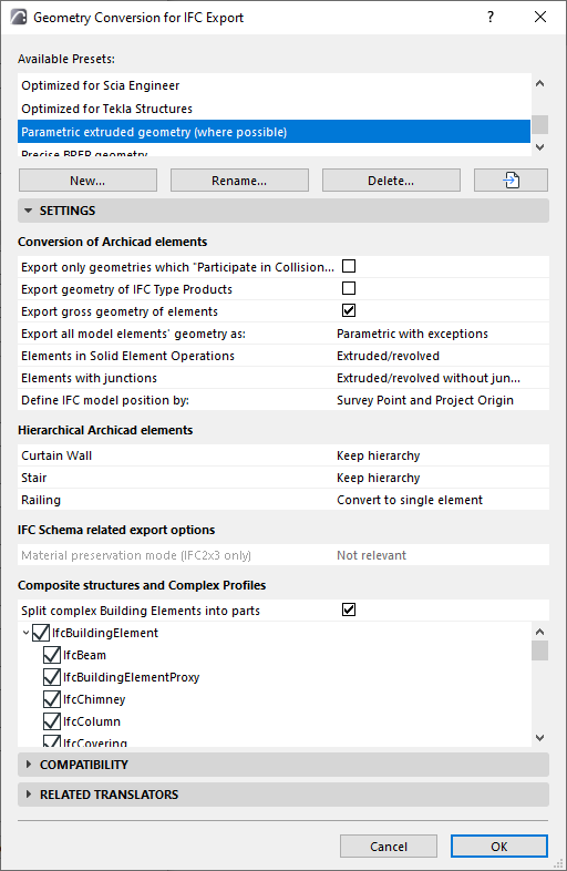
Choose a Translator for Export and open the Geometry Conversion preset.

These settings define how to convert the geometry of Archicad elements exported to IFC.
The conversion settings are divided into categories:
Conversion of Archicad Elements
Hierarchical Archicad Elements
Composite Structures and Complex Profiles
Conversion of Archicad Elements
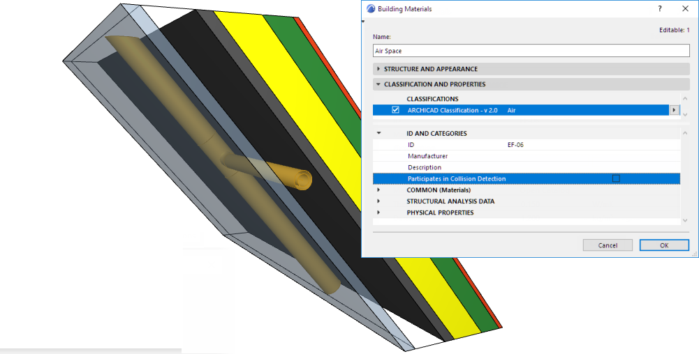
Export only geometries which “Participate in Collision Detection”
Exports only elements whose Archicad Building Material includes the “Participates in Collision Detection” option ON. (This is set at Options > Element Attributes > Building Materials > Properties).
Use this option to export composite elements and complex profiles, which don’t have solid geometries, as real air gaps. This way, MEP engineers (who receive the Archicad IFC file) can place pipes in the gaps without collision detection; only element parts which have real geometry will participate in collision detection.
See also Collision Detection.
Export Bounding Box
Exports the dimensions of the building elements’ bounding box.
Export Geometry of IFC Type Products
Assigns a representative geometry to each Type Product. (This option is required for Concept Design BIM 2010.)
Each type (e.g. IfcFurnishingElementType) will use a representative geometry of the elements that belong to it (e.g. IfcFurnishingElement).
Export gross geometry of elements (Export holes separately)
Elements containing Doors, Windows and/or Openings are exported with their gross geometry. For example, a host Wall is exported with its gross geometry, without considering the hole created by a window.
Use this option to ensure accurate cost calculation using the IFC model, where the opening geometry will be considered separately.
Note: Openings are exported by checking IfcOpeningElement in the Model Filter for IFC Export. This is generally checked by default.
If the Export gross geometry option is unchecked, then elements cannot be created using extrusion. In this case, extruded elements with holes are exported as BREP!
Export all model elements’ geometry as:
This describes how the exported element geometry will be interpreted. Choose one of the three options from the pop-up: BREP; Parametric (Extruded/revolved); or Parametric with exceptions. See below.

BREP
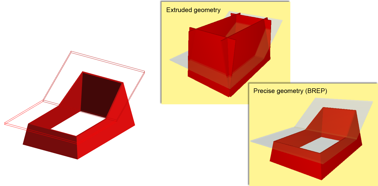
•All model elements are exported using BREP (Boundary Representation) geometry, together with their junctions.
•This method is useful in the “reference model” workflow.
•Provides the most exact reproduction of element geometry, together with its specialized sections and junctions.
•Exported elements are transformed into non-editable elements, and their parameters are lost.
•The elements will be exported in the color displayed in the current Archicad view, including colors from Graphic Overrides, Renovation Status, and Issue highlights.
Parametric (Extruded/revolved)
•All model elements are exported using Parametric (Extruded/revolved geometry.)
•This is the format usually supported by static analysis programs, in which element parameters are important, but their special cut angles (such as the slanted edge of a slab) are not important.
•Retains the elements’ parameter values (such as thickness, height, location of reference line or edge).
•The skin structure of composite materials cannot be fully preserved because of the IFC standard’s limitations.
•Certain specialized sections are not retained.
Note: Morphs, Objects, Shells and certain Walls or Beams with unusual profiles cannot be exported as parametric: these are always exported using BREP.
Parametric with exceptions

•This exports elements as parametric (as described above). However, you can set separate export preferences for Elements in Solid Element Operations and Elements with junctions (including slabs with slanted edges):
–BREP (as described above)
–Extruded/Revolved (as described above)
–Extruded/Revolved without junctions: Elements are exported without the priority-based intersections, resulting in a faster export process.
-Recommended for structural analysis programs, for which the elements’ reference lines/surface information is sufficient, and detailed intersections are not required.
Choose to locate the IFC Site entity using the Survey Point and/or Project Origin.
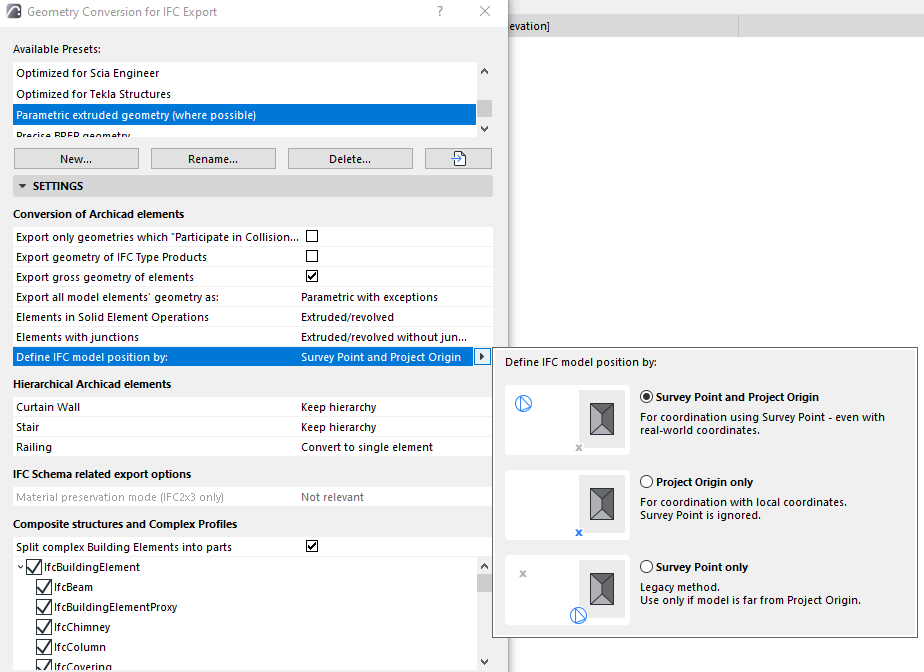
•Survey Point and Project Origin (default): Used in most coordination workflows.
•Project Origin only: Use this if model position is unimportant (e.g. to use the model to create budget calculations). This workflow is most typical in German-speaking markets.
•Survey Point only: Use this only if the model is far from the Project Origin.
Notes:
–The program considers the Survey Point even if it is not visible in the exported view
–To assign geographic property data, use the Survey Point’s Georeferencing data. These properties can be shared with any project participants via IFC.
See also Survey Point.
Note on Export of IFC Site Geometry:
As of Archicad 23, all elements that are IFC Site Geometry are exported to IFC as solid bodies.
Archicad elements are IFC Sites if they are:
•Classified using “IfcSite” as their IFC Type, or
•Saved as Objects having the Subtype “IFC Site”
Mapping IFC Location Data From Archicad and Revit
|
IFC |
Archicad 20 and up |
Revit |
|
IFC Global Origin |
Survey Point |
Survey Point |
|
Position of IfcSite entity |
Project Origin |
Project Base Point |
Hierarchical Archicad Elements
Choose a conversion option for each type of hierarchical element: Curtain Walls, Stairs, Railings.
•Convert to single element: The hierarchical element is exported as a single IFC entity, which contains within itself the geometry of all its sub-elements. The hierarchical nature of the original element (e.g. Stair, with all its separate sub-components) is thus lost.
•Keep hierarchy: Retain the original element’s hierarchical structure, including sub-elements.
See also Exporting Hierarchical Elements from Archicad as IFC Containers.
Material preservation mode (IFC2x3 only)
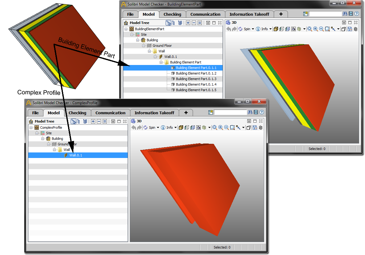
Use this control to define whether and how to explode complex elements into Building Element Parts. This choice depends on whether you need to retain the material definitions of the components.
Choose one of the following Material preservation modes:
•Never explode elements. Material preservation is not guaranteed.
This is the default option: complex elements (composites and Profiles) are not exploded, because doing so multiplies the number of Building Element parts in IFC.
•Explode only when necessary to preserve materials. The program will explode an element only if that is the only way to preserve its material definition.
•Explode all elements into parts, preserve materials. All complex elements are exploded into parts, and material preservation is guaranteed.
Notes:
–These Material preservation options are relevant for IFC2x3 only.
–For IFC4, use the control below: see Split Complex Building Elements into parts.
Composite Structures and Complex Profiles
Split Complex Building Elements into parts
Use this control to split complex elements into Building Element Parts. This option enables you to comply with IFC4 Reference View. Material definitions are not affected by this option (IFC4 retains material definitions irrespective of whether complex elements are split.)
This option enables composite elements and Complex Profiles to be split into so-called “Building Element Parts”. With this option, the receiving Structural Engineer will know that a composite Wall includes an air gap component.
If you check the box:
–the tree structure below is editable: you can choose specific element types to be split into parts. (The unchecked element types will not be split up.)
If the box is not checked: no complex elements will be split.
