Use Distance Guides to input and move elements accurately on the Floor Plan, with pop-up guides that show dynamic distances from surrounding “context” elements. You can use Distance Guides both during and after element placement.
Enable Distance Guides
Distance Guides are enabled by default.
Turn them on or off in the following ways:
•View > Distance Guides
•Options > Work Environment > Tracker and Coordinate Input
•Toolbar toggle
Set Distance Guide Preferences
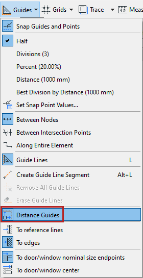
From the toolbar toggle:
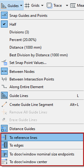
•Set whether the guides should measure from element edges, or from their reference lines
•Set which door/window reference points to use. See Door/Window Reference Points.
Which elements display Distance Guides?
The following “context” elements show Distance Guides when you select or input a standalone element:

•Grid (without the marker part)
•Wall
•Beam
•Column
Distance Guides - Priority
When several element types (visible in the current zoom) can all be used as context elements, Distance Guides “prefer” elements in the following order:
1.Grid lines
2.Walls
3.Beams
4.Columns
Use Distance Guides to edit selected element
1.Select a single element of the following types on the Floor Plan (curved elements not supported):
•Wall
•Beam
•Column
•Window/Door
•Opening
2.Edit the location of the selected element using the Tracker, taking advantage of feedback from Distance Guides.
See Element Input Using Tracker.
Note on Distance Guides with walls and beams
When using Distance Guides to "move" these elements lengthwise, they will stretch or shrink (instead of moving from one place to another). Connected walls and beams will not break as a result.
Use Distance Guides for element input
1.Activate one of the following element tools:
•Wall
•Beam
•Column
•Window/Door
•Opening
2.Define cursor location by using the Tracker. You must use the keyboard to enter the Tracker and edit the values.
3.Distance Guides indicate the perpendicular distance from cursor position to the surrounding “context” elements. (Curved elements are not supported.)
Note: The cursor position you define is the start point of the new element’s Reference line/axis.
Column End Cuts and Reference Axis
Relink Distance Guide to another reference edge
For a selected element on the Floor Plan, you can manually relink the Distance Guide to another edge.
1.Point your cursor at the arrowhead at the end of the Distance Guide line
2.Hover to see the feedback
3.Click the arrowhead to edit it
4.Click on any valid edge (any projected element edge that is parallel to the selected element, or perpendicular to the Distance Guide)
Choose which door/window reference points to use:
•To nominal size endpoints: Measures from the nominal size endpoints of selection to the nominal size endpoint of reference Door/Window element, if applicable
•To center: Measures from the center point of selection to the center of reference Door/Window element, if applicable