Standardized schematic representation for MEP Systems
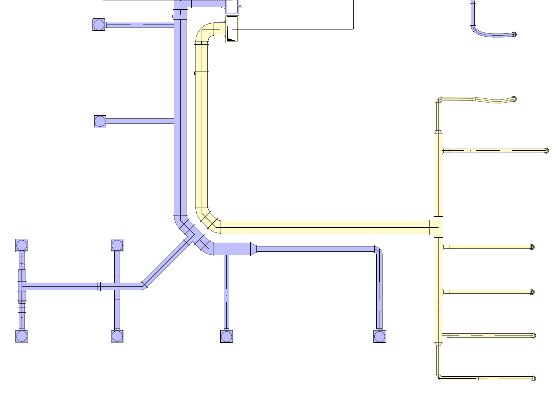
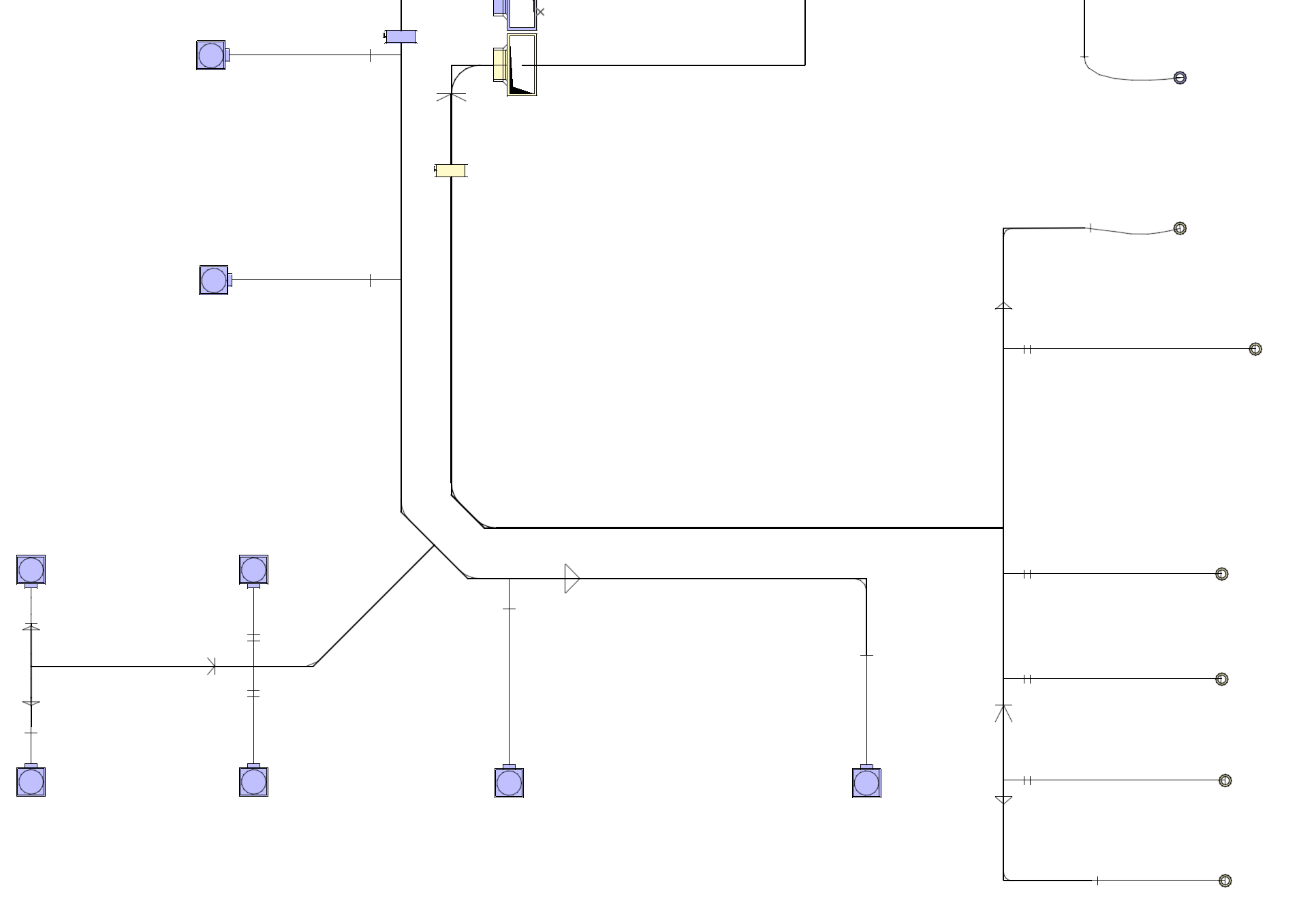
MEP Designer 30 makes it easier to produce clearer and more accurate MEP documentation, thanks to more flexible element display on 2D plans.
-
Symbolic documentation is consistent across all views and supports automated schedules and labeling
-
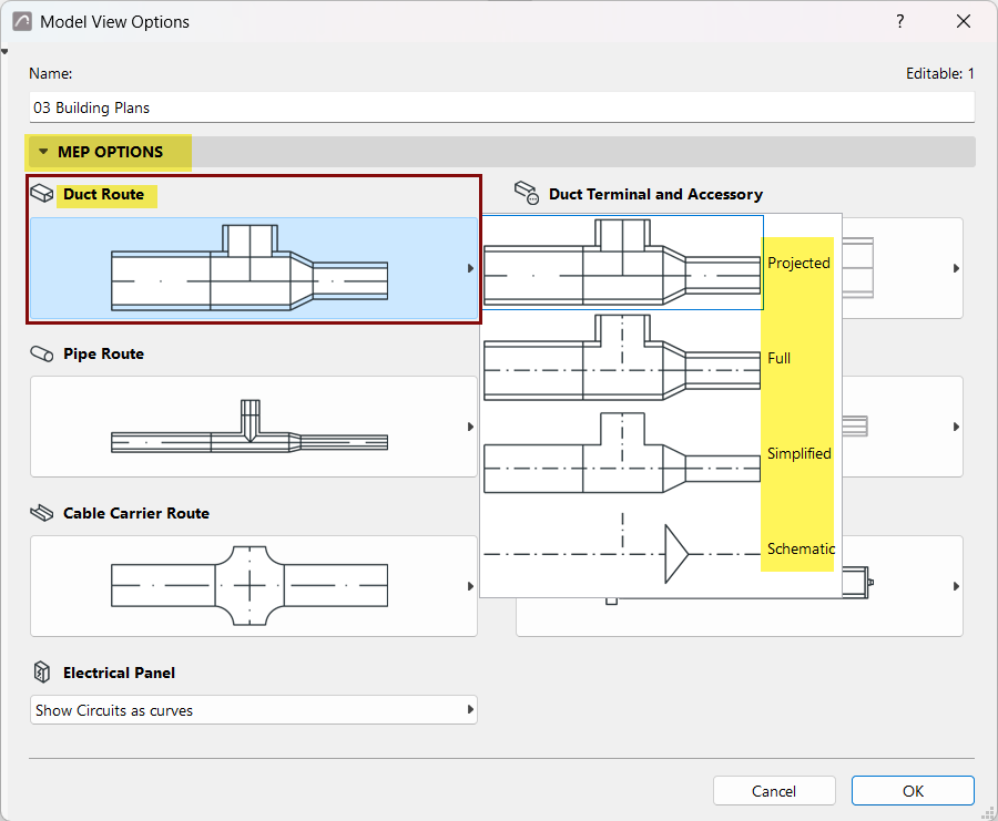
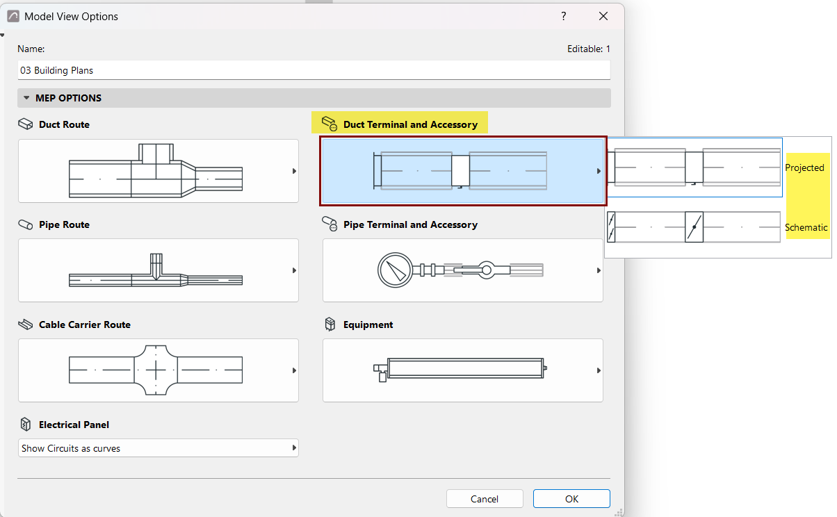
Use schematic symbols which represent the function of elements, rather than their geometry
-
Documentation output is up to standard for submission and construction, supporting industry workflows and regulatory compliance
-
If needed, override MVO for any element’s individual display
|
|
|
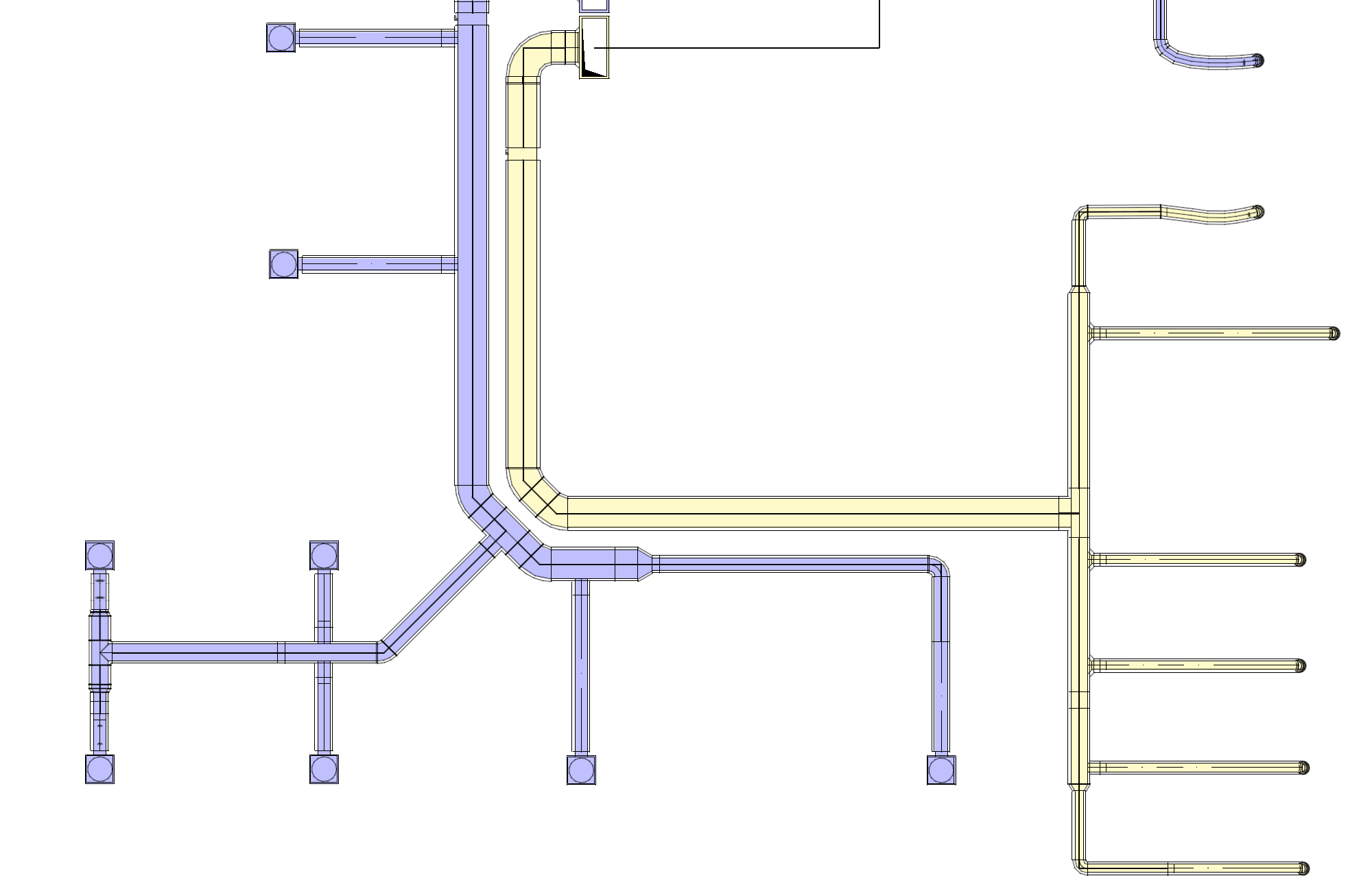
| Projected display | Simplified (no insulation) | Schematic |
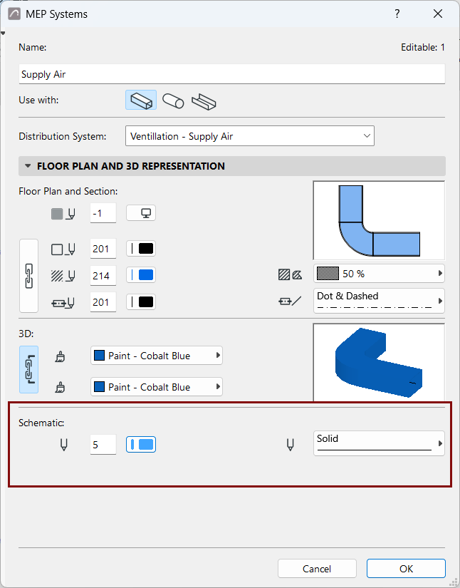
With Schematic display, define line colors by System, using MEP Systems dialog.