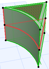
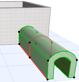
Extruded Shell with Freely Defined Profile
Use this method to define the Shell profile with a polyline, then extrude it perpendicularly to the editing plane. Two examples are shown here.
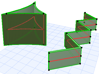
- Activate the Shell Tool and choose the extruded geometry method with detailed input method.

On the Floor Plan:
- Draw the Shell profile - a polyline or a closed polygon - with the usual polygon input method.
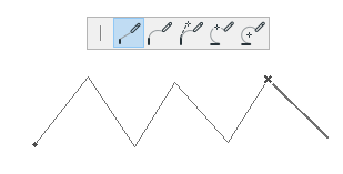
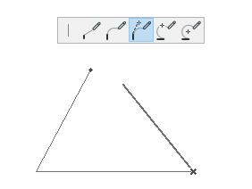
- Double-click to complete the polyline or polygon.
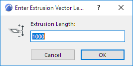
- In the appearing dialog box, enter the length of the Shell’s extrusion. A positive number will extrude the Shell upward (toward you). A negative number will extend the vector away from you. The extrusion is always perpendicular to the Floor Plan. Click OK.
- The Shell is complete. View it in 3D. (In the 3D window, the profile line of a selected Shell is displayed in a separate color.)Note: You can change this color using the “Reference Lines in 3D” setting at Options > Work Environment > Selection and Element Information.
In the 3D Window:
- Choose the input plane. Either click to find the default plane, or choose another input plane based on existing elements.
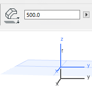
- If you click in “empty space”, the default input plane is at the base elevation defined in Shell Default Settings (here, 500).
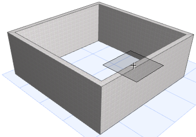
- To place an input plane defined by points or surfaces of an existing element, choose it by clicking on any points and/or edges or surfaces: The automatic feedback (a gray square) will show you where the potential input planes are. When you get the plane you want, click to make it appear.
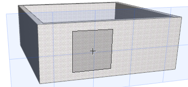
- If you click in “empty space”, the default input plane is at the base elevation defined in Shell Default Settings (here, 500).
- Draw the Shell profile - a polyline or a closed polygon - with the usual polygon input methods. (Here, two different examples are shown.)
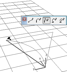
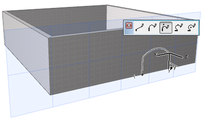
- Complete the polygon.
- Extrude the Shell by dragging the cursor. It will be extruded perpendicular to the input plane.
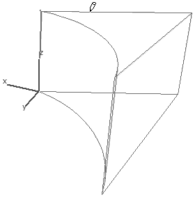
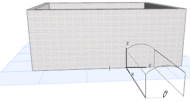
- Click to complete.