Cantilevered Flight and Landing Structure
These settings are available if you chose a Cantilever Structure type for the Flight and/or Landing.
Choose a Cantilever Component type - e.g. Bracket or Block.
Use the Cantilevered Settings Panel to configure the chosen structure:
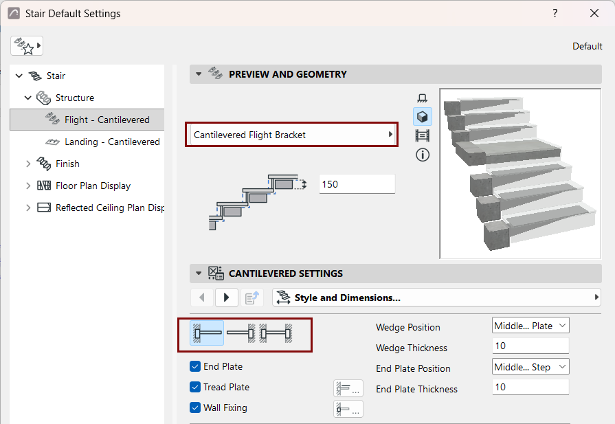
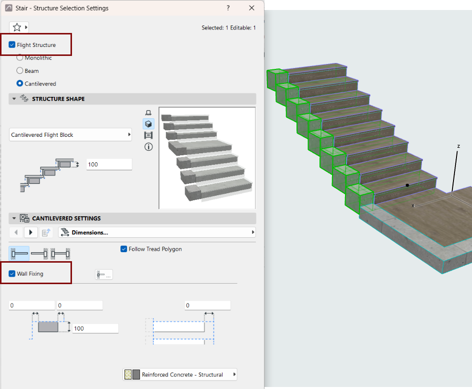
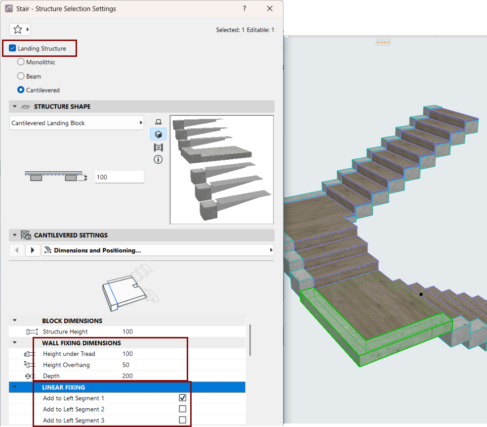
Use Edit Mode to add an optional Wall Fixing to Flight or Landing, as shown below:
Define components as Core/Finish/Other
In the Representation section of the Settings dialog: set the components as Core/Finish/Other. (When editing Beam, Cantilever, and Stringer structures: uncheck the "Uniform Component Types" to set each component separately.)
Defining component types in this way allows you to control their display via Partial Structure Display. For example, to display structure-only coordination views, choose "Core only" as the view's Partial Structure Display setting. This will hide stair components that are defined as "Finish" or "Other".