Representation of Loads
Scaling of Load Sizes (Loads on 1D Members)
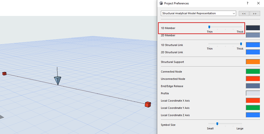
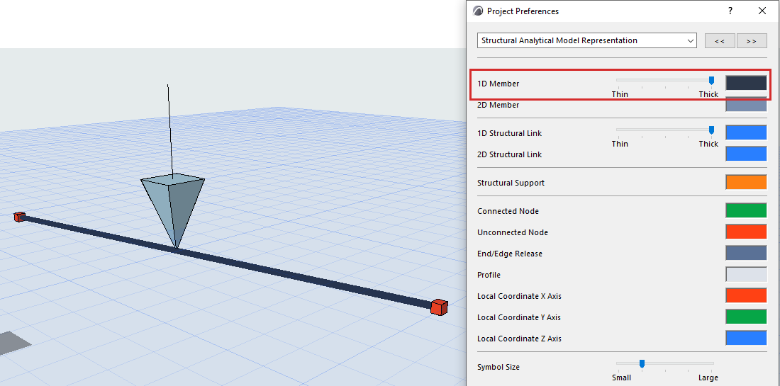
To optimize Load display, the displayed Load symbol is automatically resized based on 1D Member thickness.
1D Member thickness is set at: Project Preferences > Structural Analytical Model Representation
For example, a 1D Member with smaller thickness will display smaller Load elements.
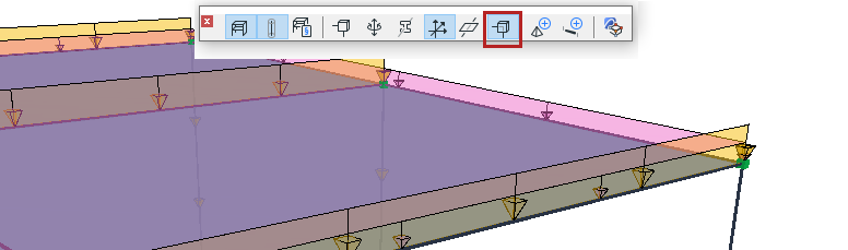
Show Point Load Arrows as Transparent
Use the “Transparent Symbols” toggle of the Structural Engineering toolbar. These affect the display of Point Load arrowheads in 3D views.
Minimum and Maximum Load Size representation
To improve visibility in the project, geometric limits have been introduced in the representation of Loads.
After reaching certain intensity limits (either the minimum or the maximum value) the size of Loads will not change.
The default limit values are as follows:
Load Tool |
Minimum Intensity |
Maximum Intensity |
Point |
1 kN |
1501 kN |
Line |
1 kN/m |
76 kN/m |
Surface |
1 kN/m2 |
26 kN/m2 |