Some Column or Beam elements can use multiple cross-sections and/or several Building Materials:
Multi-segment Beams or Columns
Tapered Beams or Columns
A single Complex Profile with different Profile Modifiers at each end
Such a Column or Beam generates a single 1D Member in the Structural Analytical Model. However, you have two options to handle the cross section export to SAF: Use a single Replacement Profile, or export all the cross sections.
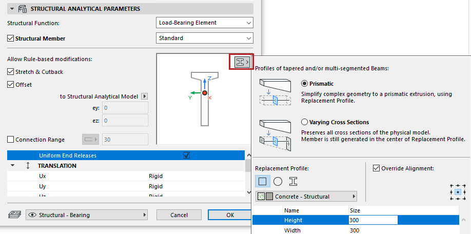
Go to the Structural Analytical Parameters panel of Beam or Column Settings.
If the element has a varied cross-section: The Replacement Profile pop-up is available in the preview window.
Choose how to export the cross-section profile(s):
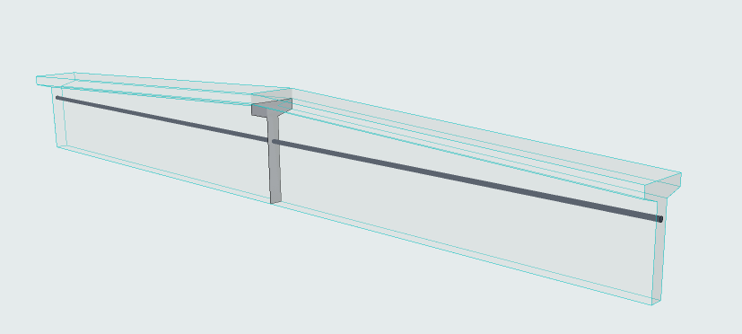
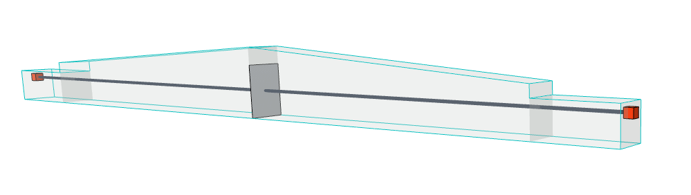
Prismatic: Export a single Replacement Profile to represents the 1D Member cross section. (Recommended for early-stage calculations of schematic design)
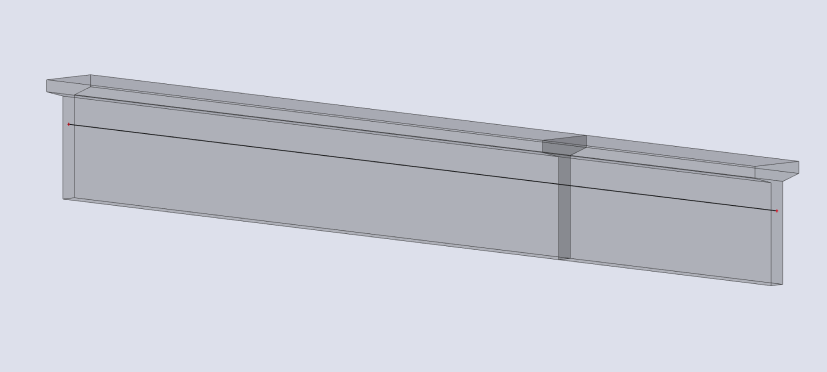
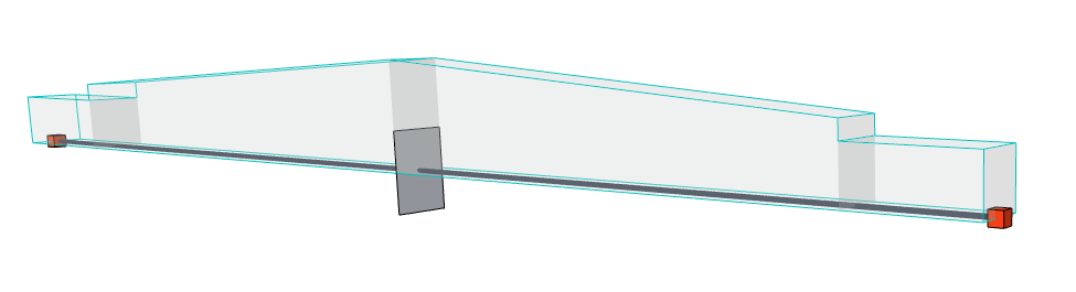
Varying cross sections: Export all the cross sections of the 1D element, preserving all details of the physical model. (Recommended for project stages where precise calculations are needed).
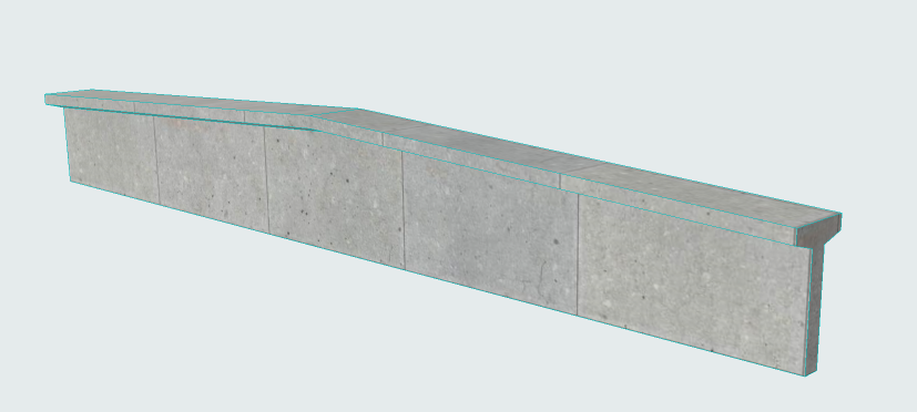
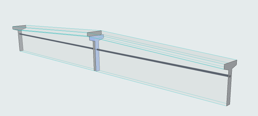
Figure 1. Original physical model in Archicad
Prismatic (Export using single replacement profile)
Prismatic export in analysis software
Figure 2. Varying cross sections (Export all cross-sections)
Varying cross sections in analysis software
Choose a structure for the Replacement Profile core: Rectangular, Circular, or Complex Profile
For a Complex Profile structure:
Choose a Profile and set editable parameters (if any). The list includes:
Profiles available for Column or Beam (as applicable)
Profiles that include at least one core component
For a Rectangular or Circular structure:
Choose Building Material and dimensions
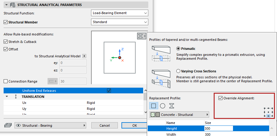
Override Alignment of Replacement Profile
Available with Prismatic option.
By default, the Replacement Profile origin is inserted at the Member's reference line.
Figure 3. Default position of Replacement Profile
If needed, realign the Profile Origin to better reflect the architectural model. Check the Override Alignment box, then choose a different anchor point:
Figure 4. Override position of Replacement Profile
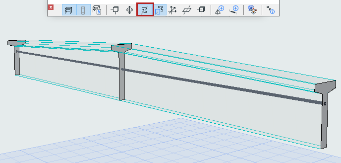
Show Profiles of Load-Bearing Cores
Turn on this option (from the Structural Analytical Model toolbar).
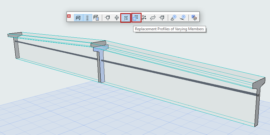
Replacement Profile for Varying Cross Sections: Position of 1D Member
For varying cross sections, the Replacement Profile is used only to position the 1D Member, which is generated in its center. To see this Replacement Profile, turn on the toggle.
(The Show Profiles toggle must also be on.)
Use this display option to understand how the 1D Member is positioned in a varying cross-section.