Built-in floor plan symbols are provided for numerous MEP elements.
Note: Use Model View Options to display MEP elements on the Floor Plan as Symbolic or Projected: see Symbolic representation of MEP elements)
If you prefer a customized symbol, you can edit the built-in symbol or draw your own.
Note: Custom MEP symbols can be used with Pipe Terminals, Pipe Accessories, and Equipment.
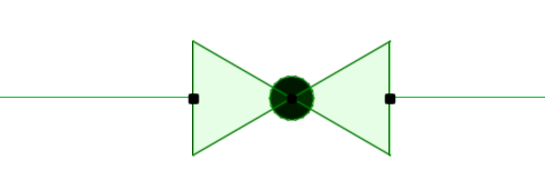
For example, here is the built-in symbol for a pipe valve.
To create a valve symbol that has a handle:
1.Do one of the following:
•Copy and paste the existing 2D symbol into a Worksheet (or Floor Plan)
•Draw a new symbol using 2D drawing elements (e.g. lines, fills)
2.Select your new symbol drawing.

3.Use File > Libraries and Objects > Save Selection As > MEP Symbol.
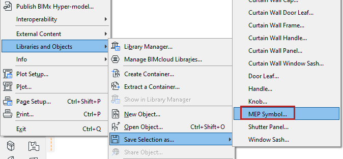
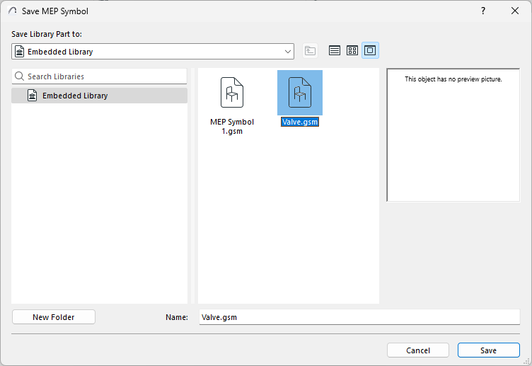
4.Enter a file name and location, then click Save.
•The default location is the Embedded Library, but if you have a large number of MEP Symbols, it is useful to organize them into named subfolders.
5.In the model, select the MEP object symbol to be replaced (for example, this valve) and open its Object Settings.
6.On the MEP Custom Settings page, go to the Visualization tab.
Instead of the Built-in Plan Symbol, choose Custom Plan Symbol.
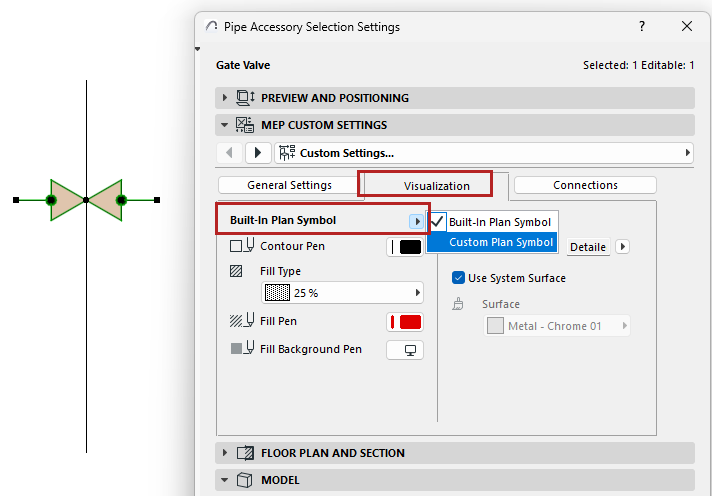
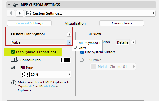
7.From the popup, choose your saved Custom MEP Symbol.
–The Keep Symbol Proportions box is checked by default, to avoid distortion in object display
8.The valve is now displayed using your custom MEP symbol.

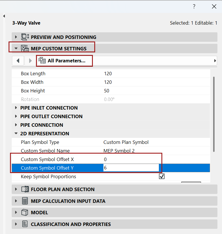
Adjust alignment of custom symbol - use Offset parameters
If the new symbol is not positioned correctly in the plan:
1.Select the symbol.
2.Open Object Selection Settings.
3.Go to MEP Custom Settings and open the All Parameters list.
4.Use the Custom Symbol Offset X and Y parameters to adjust the Object’s position.