Note: For Doors and Windows created with Library Part Maker, the
opening-line type cannot be set individually for each element through Model View Options. An
LPM Door always uses a Type 1 opening line, while an LPM Window always uses a Type 3 opening
line.
Selected 3D Detail Level
Default LOD
Substitute LOD 1
Substitute LOD 2
Substitute LOD 3
Full
Full
Simplified
Schematic
System empty opening
Simplified
Simplified
Schematic
Full
System empty opening
Schematic
Schematic
Simplified
Full
System empty opening
Door/Window Component Origins
A special methodology applies in case of Door and Window Library Parts.
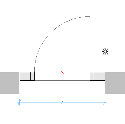
Component origins for 2D door/window symbols must be aligned with
the center of door/window wall opening and the external edge of wall they will be placed
in.
Component origins for 3D door/window models must be aligned with the
bottom center of door/window wall opening.Figure 1. Door Symbol with Component Origin at Hotspot
Definition of Door/Window Tolerance
LPM Assignment
Content shown with corresponding Model View Option (MVO): Detail Level of Door,
Window and Skylight Symbols
2D Tolerance Full
Floor Plan Symbol Full
2D Tolerance Medium
Floor Plan Symbol Medium
2D Tolerance Low
Floor Plan Symbol Low
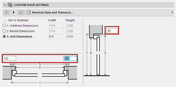
The Wallhole is the part cut out of the wall to accommodate the whole
door/window structure.
Wallhole Width is equal to Unit Dimension Width plus any Horizontal
Tolerance.
Wallhole Height is equal to Unit Dimension Height plus any Vertical
Tolerance.
Figure 2. Tolerance Values in Door Custom Settings
Design Principles of Tolerance
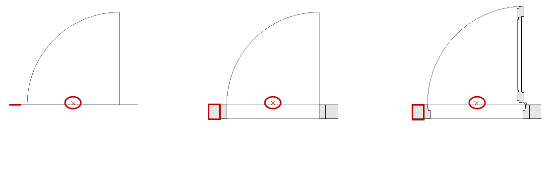
The tolerance 2D symbol must always be drawn (using Archicad 2D tools)
on the left-hand side of the door/window 2D symbols, with the same width for all used 2D
symbols in a door/window Library Part.
The 2D tolerance symbols will be automatically added to right, top and
bottom door/window edges, and they will be parametrically adjusted to Wallhole edges. The 3D
model will be created automatically, based on the tolerance width defined in 2D Symbol and
the door/window frame thickness. The tolerance width and tolerance surfaces will be
automatically added to the door/window user interface as parametric values.
Figure 3. Tolerance Displayed at Low, Medium and Full LOD Assignment
Opening Lines, Hinges and Handles
LPM Assignment
Content shown with corresponding Model View Option (MVO): Miscellaneous
Settings for Library Parts
Opening Line Hinges Full
Show Opening Line (Hinges orientation, Full 3D)
Opening Line Hinges Simplified
Show Opening Line (Hinges orientation, Simplified 3D)
Opening Line Hinges Schematic
Show Opening Line (Hinges orientation, Schematic 3D)
Opening Line Handle Full
Show Opening Line (Handle orientation, Full 3D)
Opening Line Handle Simplified
Show Opening Line (Handle orientation, Simplified 3D)
Opening Line Handle Schematic
Show Opening Line (Handle orientation, Schematic 3D)
Design Principles of Opening Lines, Hinges and Handles
Figure 4. Handle Opening Line orientation
Figure 5. Hinges Opening Line orientation
LPM allows to define any number and directions of Opening Lines and/or
Opening Operation symbols in 3D Models by using 3D Archicad tools. The 3D opening lines can
be defined by Morph tool (set to the Line Geometry Method).
It is also possible to use e.g. the 3D Text Library Part (from standard
Archicad library) to define any fixed text annotations.
Considering the varying standards for the direction of opening lines,
LPM provides 2 sets of assignments that define opening line orientation as either “Hinges”
or “Handle”.
The Opening Line Orientation control (available in Model View
Options and the Library Part user interface) allow the user to flip their positioning as
needed.
Positioning of Door/Window Handle Assembly
Note that the option for 3D Handle assembly is available for “3D Model
Full” LOD only.
LPM Assignment
Content use
Handles Internal Full
Used for Handle assembly on internal face of opening
Handles External Full
Used for Handle assembly on external face of opening
LPM allows definition of any number and directions of Handle assembly
types, separate for interior and exterior faces of an opening. The type of Handle assembly
can be selected from standard Archicad types or any Custom Component Handle Library Parts
(in loaded libraries).
Design Principles of Handle Positioning
Use the 3D lines that can be defined by Morph tool (set to the Line
Geometry Method)
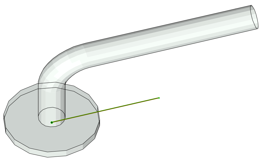
Definition (Morph line)
Figure 6. Morph Origin
The morph origin will be used as the anchor point (in 3D space, so the
morph line must be positioned on door/window surface), and the direction of the line will be
used as the Handle assembly’s orientation. The length of the line does not affect the final
handle position or shape. The relationship of a morph line used for design and the final
Handle model is illustrated below:
The assignment type will define handle orientation with regards to
Internal or External face of a door or window.
The following standard Archicad library door or window parametric
elements and functionality will be added to each door or window automatically:
Windows
Wall Opening – Reveal
Wall Opening – Wall Closure
Wall Opening – Wall Inset
Wall Opening – Masonry Arch
Wall Opening – Attributes
Fixtures & Fittings – Sill
Fixtures & Fittings – Board
Fixtures & Fittings – Casing Inside/outside
Fixtures & Fittings – Sunshade
Fixtures & Fittings – Custom Corner
Fixtures & Fittings – Attributes
Door
Wall Opening – Reveal
Wall Opening – Wall Closure
Wall Opening – Masonry Arch
Fixtures & Fittings – Threshold
Fixtures & Fittings – Casing Inside/outside
Fixtures & Fittings – Sunshade
Fixtures & Fittings – Attributes
System predefined parameters for Doors and Windows
Width – width of Door/Window set
Height – height of Door/Window set
Nominal Frame Thickness – frame thickness of Door/Window set
Orientation Displaying – If set to ‘Automatic’, Label Default
Position and Label Reversed Position values will be used for Door/Window labels and in
Interactive Schedules. If set to ‘Custom’, the value of Custom Orientation parameter will
be used instead.
Custom Orientation – used in conjunction with Orientation Displaying
parameter
Label Default Position – (set to ‘L’ for ‘Left’ by default) used in
conjunction with Orientation Displaying parameter
Label Reversed Position – (set to ‘R’ for ‘Right’ by default) used
in conjunction with Orientation Displaying parameter