Model Appearance (Section-Type Views)
Use the Model Appearance Panel of Section Settings to define the appearance of the model in a Section-type view.
Available for Source-type Sections and Elevations, 3D Documents and Interior Elevations.
Use the following controls:
ELEMENT CONTOURS AT SECTION/ELEVATION BOUNDARY
See also:
Note on Transparent Fills in Plotter Output
Display of Elements in Interior Elevation
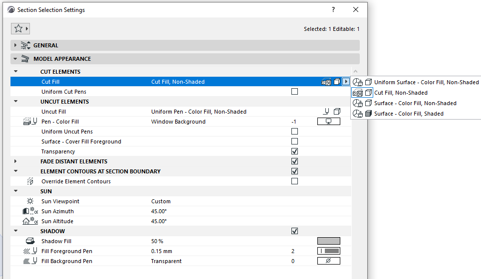
CUT ELEMENTS
Choose how to display cut elements in this Section.
|
CUT FILL OF ELEMENTS IN SECTION |
|
|
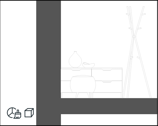
Uniform Surface - Color Fill,Non-Shaded
Use a single surface to display all cut elements. Use the Surface - Color Fill control to choose the color. 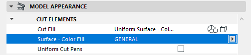 |
 |
|
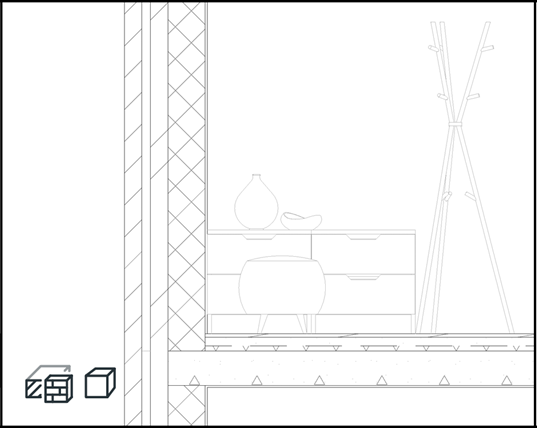
Cut Fill, Non-Shaded
Cut fill of Building Material |
 |
|
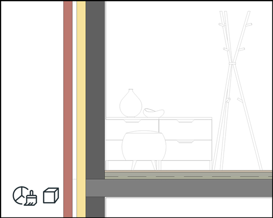
Surface - Color Fill, Non-Shaded
Surface of Building Material |
 |
|
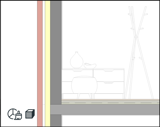
Surface - Color Fill, Shaded
Surface of Building Material |
 |
Uniform Cut Pens
Use the same pens for all cut elements (cut line pen and fill foreground/background pens, as applicable).
UNCUT ELEMENTS
Choose fill attributes for uncut elements.
|
UNCUT FILL OF ELEMENTS IN SECTION |
|
|
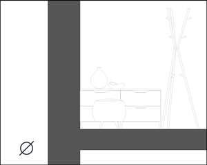
Nothing
No color applied to uncut surfaces. |
 |
|
Uniform Pen - Color Fill, Non-Shaded
Fill all uncut surfaces with a single color. Use the Pen-Color Fill control to choose the color. 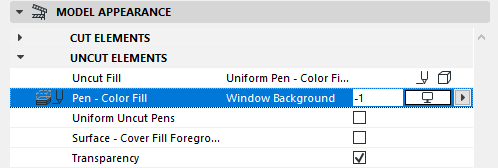 |
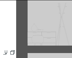 |
|
Surface - Color Fill, Non-Shaded
Surface of Building Material (no shading effect) |
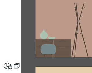 |
|
Surface - Texture Fill, Non-Shaded
Surface plus texture of Building Material (no shading effect) |
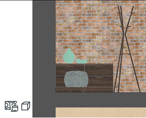 |
|
Surface - Color Fill, Shaded
Surface of Building Material (with shading effect) |
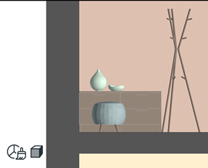 |
|
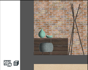
Surface - Texture Fill, Shaded
Surface plus texture of Building Material (with shading effect) |
 |
Uniform Uncut Pens
All uncut lines use the same pen. Choose the desired pen from the Uncut Line Pen picker, below.
Surface - Cover Fill Foreground
Also activate the Cover Fill foreground of the surface. (Can be defined for each Surface attribute.)
Transparency
Display see-through surfaces (e.g. glass) as transparent.
FADE DISTANT ELEMENTS
Check this box to divide the Section into “close” and “distant” areas.
You can then differentiate the distant area by applying a separate fill to it.
To define the limit where “close” ends and “distant” begins, go to the Floor Plan and drag the “distant” marker line.
The “distant” marker line is an on-screen-only element.
ELEMENT CONTOURS AT SECTION/ELEVATION BOUNDARY
Check this box to apply a contour to any displayed element which extends past the Section´s horizontal limit.
This contour marks the element's boundary, as it is shown in the section, even though the element does not really end there.
Choose a Line Type and Pen for the contour.
SUN
Choose one of two sun positions relative to the Section/Elevation Line:
- As in 3D Window: Use this option to inherit the sun position set up in the 3D Projection or 3D Perspective Settings dialog box.
See also 3D Window.
- Custom: Use the Sun Azimuth/Sun Altitude controls below to define a custom sun position for this Section/Elevation.
Sun Azimuth
The Azimuth value is an angle value in degrees. The line that is at a right angle to the Section/Elevation line represents zero degrees. As I increase the azimuth by increasing this angle value, the sun moves toward the right - meaning the shadows start to lengthen to the left of the shadow-casting surfaces.
If you do not want the visible side of the building to be overshadowed, you should use an Azimuth value between -90 and +90 degrees.
SHADOW
Check this box to activate Shadows (or Shadow effect).
Shadows have no contours, but you can customize their appearance.
Choose a Fill and Fill Pens for the Shadow. These can be different for Uncut and Distant elements.
Note on Transparent Fills in Plotter Output
Plotters cannot handle transparent Fills. In Texture-type fills, shadows and shading are based on transparent Fills - these will appear as solid Fills in plotter output.
In fills based on Surface Color, shadows and shading are created using color mixing, and are not affected by this limitation - they will look good on plotter output, too.