MEP Model Check for zone ventilation
For a MEP model, you can define ventilation requirements by zone. Then use built-in checks to ensure that your MEP elements (terminals or equipment) provide the required supply and exhaust air flow.
Step 1: Set up zones with ventilation parameters
Create the needed zones in the model.
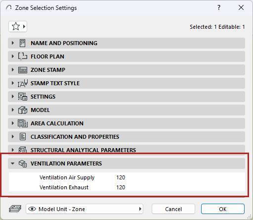
In Zone Settings, enter values for its Ventilation Air Supply and Ventilation Exhaust parameters:
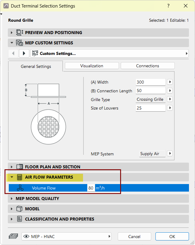
Step 2: Set up terminals or equipment with volume flow parameters
Step 3: Define System for Quality Check
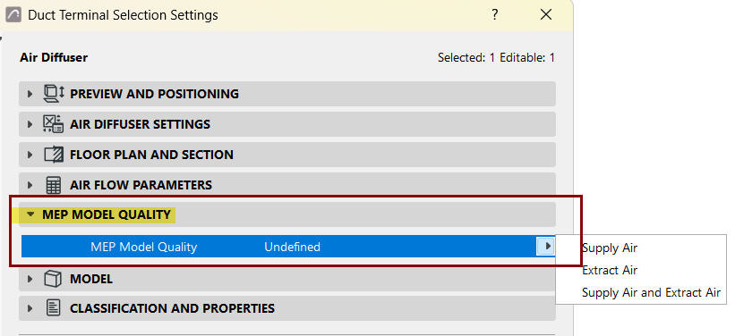
In the MEP Model Quality panel:
Choose Supply Air, Extract Air, or both to define this data for the purposes of the MEP Model Quality Check. (This is necessary because the element's MEP System, assigned elsewhere, is a project attribute that might be renamed at any time.)
Step 4: Run the MEP Model Quality Check
Run a check to ensure that the terminal/equipment placed in the model meets the zones’ parameters for adequate ventilation. The check will consider any terminal/equipment that is partially or fully placed inside a zone.
- In the 3D/Floor Plan/Section window:
- Check which parameters (air supply, exhaust, or both) you wish to check in your zones.
- Click Check.
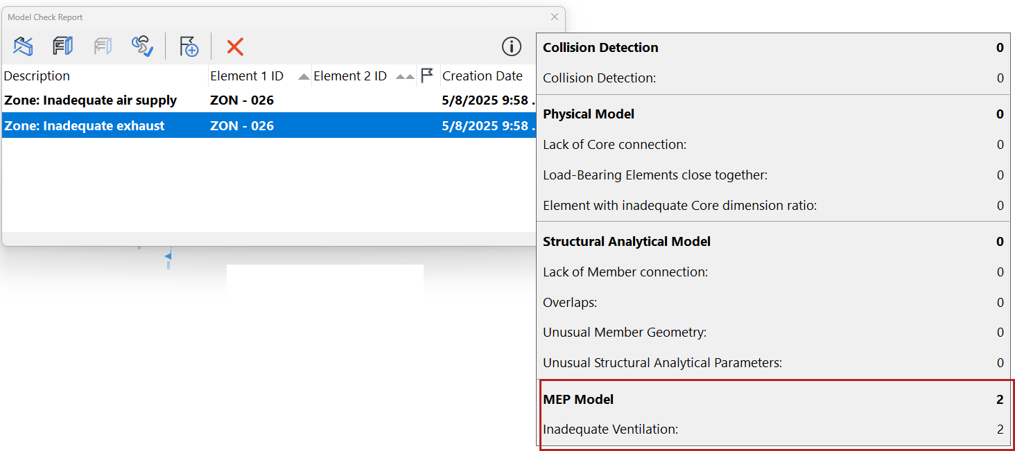
The Model Check Report lists any zones whose ventilation parameters are not met. View the related elements in the model and create Issues as needed.
Create Schedule of Zones and their ventilation requirements
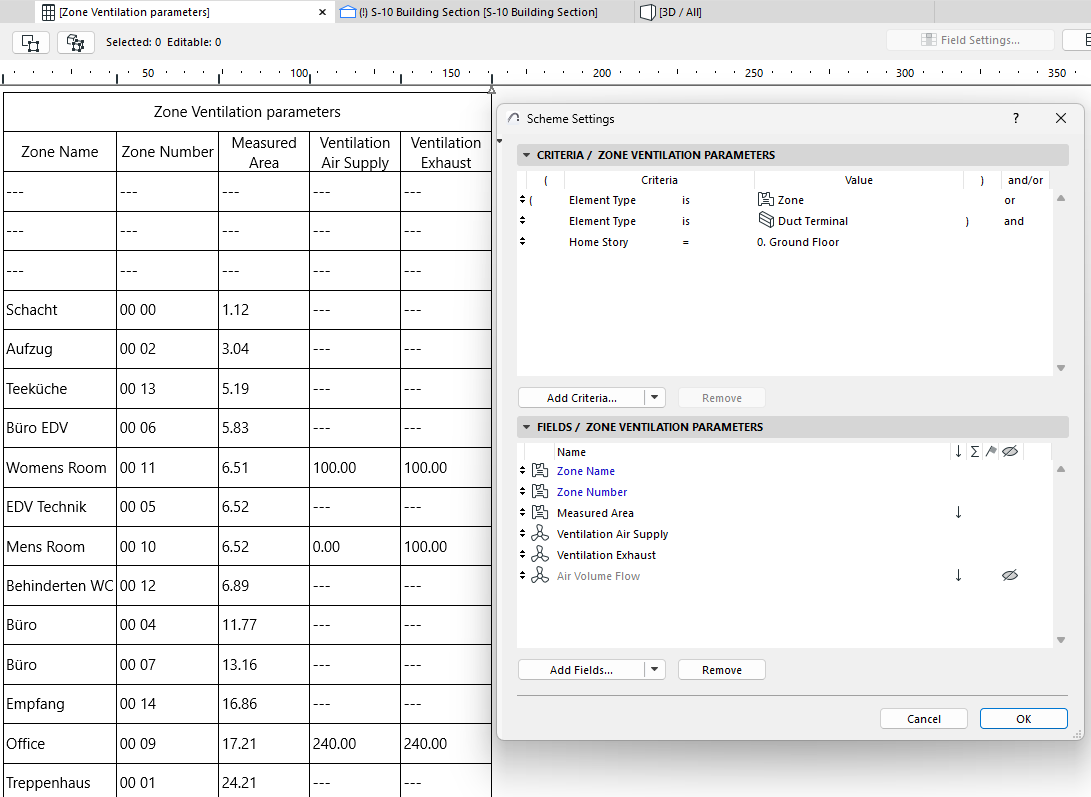
You can also list zones, their ventilation requirements, and volume flow of the relevant terminals and equipment in the Interactive Schedule.
Check and edit values directly in the Schedule, as needed.