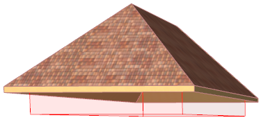
The trimming element is always either a Roof or a Shell. The Roof/Shell has a “trimming body” attached, which represents the direction and shape in which it will execute the trim on the other element(s).
Since a Roof/Shell shape is often quite complex in itself, it may be difficult to visualize exactly what will happen when you embark on a Trim operation. To see these trimming bodies while you work (in the 3D window only), turn on Trimming Bodies in the View > On-Screen View Options menu.
Note that all the trimming bodies (except the “editable” one for Shells), in fact represent bodies that are extended infinitely upward or downward (this is not shown in the feedback).
By default, the Roof’s trimming body is “Pivot lines down”, that is, the pivot line is the boundary of the trimming body, and the body extends downward from there.

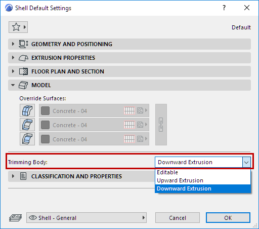
For a Shell, the default body is defined as “downward extrusion” from the Shell membrane.

However, you can change the geometry of this trimming body in Roof or Shell Settings: use the “Trimming bodies” control in the Model panel of Shell (Roof) Settings.
The trimming body options are illustrated here for both Roofs and Shells:

Pivot Lines down - Contours down

Downward extrusion - Upward extrusion - Editable
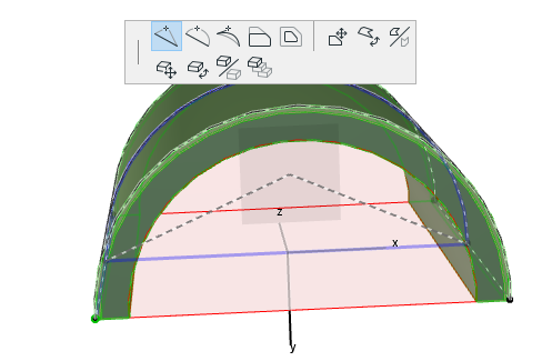
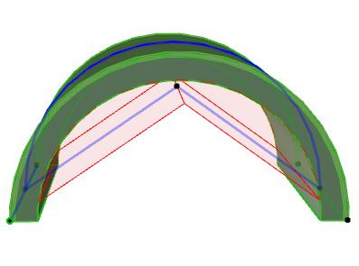
Editable Trimming Body (Shell)
For a Shell whose trimming body is set to “Editable”, the selected Shell will show a line connecting the two ends of the Shell profile. (This line represents the limit of the trimming body.) This line is editable, allowing you to change the shape of the trimming body.


Note: If you created a profile that is a closed polygon, you cannot edit this bottom line.