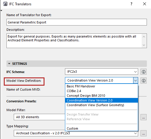
A Model View Definition, MVD (or IFC View Definition) is a recommendation for which data and elements the IFC model should include, depending on the purpose of the model exchange.
Model View Definitions are either defined within buildingSMART International, or by other organizations and interest groups.
Archicad IFC Export and Import supports the following Model View Definitions (choose an MVD in the Translator for Export Settings):

IFC2x3 Schema
•The Coordination View is currently the most widely implemented view of the IFC Schema. Its main purpose is to allow sharing of building information models among the disciplines of architecture, structural engineering, and building service. It contains definitions of spatial structure, building, and building service elements. Archicad is certified for both import and export of the latest version: IFC2x3 Coordination View 2.0.
•The IFC2x3 Coordination View (Surface Geometry) is a simplified publishing format (i.e. a subset) of the Coordination View. This format is suitable for viewing (since all IFC viewers support this format), design coordination, clash prevention during design, and clash checking, similarly to IFC4 Reference View. “Coordination View (Surface Geometry)” means that every element will be exported with its BREP (boundary representation) geometry. This method comes closest to reproducing the real shape of the element, together with its specialized sections, connections and solid operations. (However, the element’s parameters are lost, and BREP elements from an imported IFC file are transformed into non-editable elements.)
•The IFC2x3 Basic FM Handover View is an extended version of the Coordination View (developed by buildingSMART) that defines the general requirements for design applications to enable the handover of facility management information. The basic scope can be summarized as the space and equipment list for the spatial and technical systems of a facility. Technically, the Basic FM Handover View fulfills the following requirements above and beyond those of the abovementioned Coordination View: ability to assign furnishing and equipment components to spaces (Space Containment, IFC System), to assign spaces to zones (IFC Zone), to assign a classification to spaces and components (Classification Reference), to assign manufacturer base properties to components (standard and custom IFC Properties), to assign doors and windows to spaces (Space Boundaries), to assign type information for components (IFC Type Product) and to export base quantities for all project components and spatial structures. This MVD is required in various projects defined by buildingSMART and other organizations. An example is the COBie (Construction-Operations Building information exchange), a specification used in the handover of Facility Management information. It is a spreadsheet data format for the delivery of a subset of building model information, rather than geometric model information. Archicad’s BIM-quality models and IFC data exchange capabilities produces data output that is easily converted into COBie documentation, with the help of free or commercial conversion programs.
•There are several other Model View Definitions (generally the extended versions of the Coordination view) specified by organizations or development teams outside of buildingSMART International.
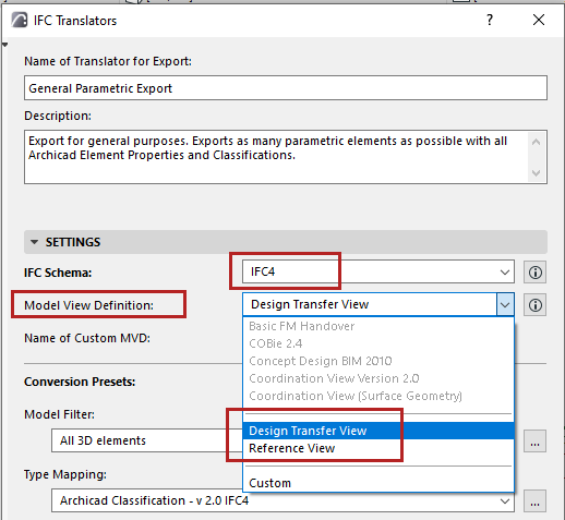
IFC4 Schema

The IFC4 Schema further divides the Coordination View into two Model View Definitions:
Note: The IFC4 Schema is not supported by all applications. Use an MVD of the IFC4 Schema only if you are certain that it is supported by the application that will receive IFC data.
•IFC4 Reference View: Suitable for all BIM workflows based on reference models, where the exchange is mainly one-directional. Requested modifications of the BIM data, mainly of the shape representation, are handled by a change request to the original author.
–When exporting to IFC4:
-the relation connections of chained Walls and Beams are omitted
-Surfaces of Building Materials are omitted
•IFC4 Design Transfer View: Provides building information with support for editing of interconnected elements: inserting, deleting, moving, and modifying physical building elements and spaces, within the limited scope of parametric exchange. An example of a target scenario is an architect providing building design information to an engineer for a particular discipline, where geometric modifications may be needed. Note that the Design Transfer View is not meant for round-trip model exchange scenarios.
All Model View Definitions can be extended by definitions which support additional exchange requirements:
•the Quantity Take-off add-on view adds the ability to transmit base quantities for all spatial and building elements
•the Space Boundary add-on view adds building elements to space relationships to support models in thermal and energy analysis
•the 2D Annotation add-on view supports the exchange of additional 2D element representations and annotations of building models