1.Activate the Opening tool.
![]()
2.In Opening Settings or the Info Box, define the Opening’s basic geometry, shape and anchor point, as needed. (Settings are described below.)

3.Hover over the associated element (e.g. Wall) into which to place the opening. The pre-placement highlight indicates the geometry of the Opening and its associated element.
If the cursor is above several potential associated elements, use Tab to cycle the highlight among them.
Notes:
–Even if the host element is part of a Hotlink Module or reserved by another user - you can place the Opening.
–Opening geometry is measured relative to its associated element, and moves along with it.
4.Click to place the Opening, depending on its shape and Orientation (see below).
Shape
Choose an Opening shape: Rectangular, Circular, Polygonal.
•If you edit the shape of a rectangular or circular Opening, it changes automatically to Polygonal.
Exception: An ellipsis Opening does not become a polygon.
•You can also use the Magic Wand to place a Polygonal opening.
Orientation defines the Opening extrusion relative to the associated element: Aligned, Vertical, Horizontal or Custom.
Aligned (default)
Aligned Opening is perpendicular to the host element’s reference line or plane, in the most logical direction depending on the host:
•Opening in a Slab or Mesh is vertical
•Opening in a straight Wall or Beam is horizontal
•Opening in a slanted Wall is perpendicular

An Opening placed with the Aligned method remains connected to the host element’s reference line or plane.
Vertical
Examples of vertical Openings:

Horizontal
Click once to place the horizontal Opening, then click again to define extrusion direction:


Custom
Drag, mirror or rotate an existing Opening into any position.
•Available for a selected, existing Opening. (Not available as default input method.)
•You can change a selected Custom-oriented Opening, then change its orientation to Aligned, Vertical or Horizontal. However, the previous Custom orientation is now lost.

By default, an Opening extends infinitely - as set at the Limits option in Info Box or Opening Settings.

An “infinite” Opening means that its length does not depend on the cut element’s geometry: if Wall thickness is increased, the Opening still cuts through it.
An Opening can also be defined as limited on one or both sides.
See Use Limited Opening to Create Niche or Recess.
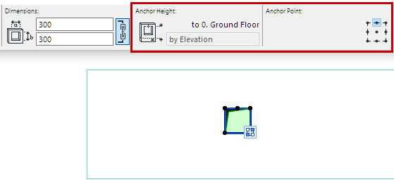
Position the Opening’s Anchor Point at any of the 9 points on the bounding rectangle.
In 3D, the blue extrusion vector indicates the anchor point’s position.
•If you resize the Opening numerically, the anchor remains fixed.
•If you resize the Opening graphically, the Opening centerpoint remains fixed - regardless of the anchor.

Opening elevation is measured from the associated element’s Home Story to the Opening’s Anchor point. This is the anchor height value.
•In 3D: Click to place the opening graphically at any elevation.
•On Floor Plan:
–Opening’s anchor height in a vertical element (e.g. Wall) is measured to the associated element’s home story.

–When placing an Opening placed in a Beam, anchor height is indicated from the story above.

–For an Opening placed in a Slab or Mesh: anchor height follows the elevation of the host element.
