Parameter
Short Description
Long Description
Parameter
Surface Area of the Shell Opposite to Reference Side (Conditional)
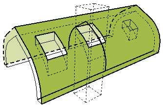
Surface area of the side opposite the Reference side of the Shell - this area may be conditioned on a defined Calculation Rule.
Reference side: The Shell membrane (the "top" of the Shell.) For a Composite Shell: The first listed skin of the composite structure, in Composite Settings.
Condition: Subtracts the area of holes only if they exceed a given size, as defined in Options > Project Preferences > Calculation Rules
Reduced by trims and SEO's.

Distortion Angle
For an Extruded Shell: Angle of the Shell profile, measured to the Shell plane. By default: 90 degrees, but changing it enables you to extrude the Shell profile at a angle, creating a distorted Shape Shell.
For a Revolved Shell: Angle of the axis of the revolved Shell, measured to the Shell plane angle.
Distortion angle value is set in the Extrusion Properties or Revolution Properties panel of Shell Settings or in the Info box.

Dome Connection length
Length of edges whose Type is set to "Roof Transition - Dome" in the Custom Edge Settings dialog box.
Typically, the edge of two adjacent Shell planes forming a convex angle.
Eaves Length
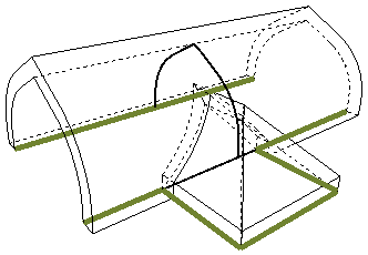
Total length of all edges whose Type is set to "Eaves," in the Custom Edge Settings dialog box.

End Angle
For an extruded Shell only. Angle of the Shell profile, measured to the Shell's inclination angle, at the second end of the extruded Shell. End angle value is set in the Extrusion Properties panel of Shell Settings or in the Info box.

End Wall Connection Length
Total length of all edges whose Type is set to "End Wall" in the Custom Edge Settings dialog box.
Typically, this is an edge which joins a Wall and slopes down along the Wall.

Gables Length
Total length of all edges whose Type is set to "Gable" in the Custom Edge Settings dialog box.

Geometry Method
Geometry method used to create the Shell: Extruded, Revolved, or Ruled

Surface Area of the Shell Edges (Gross)
Surface area of the Shell edges, including the surface of any holes.
Reduced by trims. SEO's are ignored

Surface Area of the Shell Opposite to Reference Side (Gross)
Surface area of the side opposite the Reference side, including the surface of any holes.
Reduced by trims. SEO's are ignored

Surface Area of the Shell Reference Side (Gross)
Surface area of the Reference side of the Shell, including the surface of any holes.
Reference side: The Shell membrane (the "top" of the Shell.) For a Composite Shell: The first listed skin of the composite structure, in Composite Settings.
Reduced by trims. SEO's are ignored.

Hips Length
Length of edges whose Type is set to "Hip" in the Custom Edge Settings dialog box.
Typically, the edge of two adjacent planes that meet as a hip
Holes Surface Area
Total surface area of all holes in the Shell.

Hollow Connection Length
Length of edges whose Type is set to "Roof Transition - Hollow" in the Custom Edge Settings dialog box.
Typically, the edge of two adjacent Shell planes forming a concave angle.
Surface Area of the Shell Edges (Net)
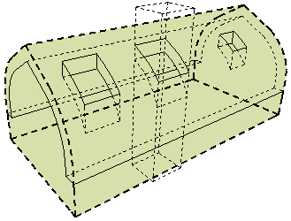
Total surface of all edges of the Shell
Reduced by holes, trims and Solid Element Operations.
Surface Area of the Shell Opposite to Reference Side (Net)
Surface area of the side opposite the Reference side of the Shell
Reduced by holes, trims and Solid Element Operations.

Net Surface Area of the Reference Side
Surface area of the Reference side of the Shell
Reference side: The Shell membrane (the "top" of the Shell.) For a Composite Shell: The first listed skin of the composite structure, in Composite Settings.
Reduced by holes, trims and Solid Element Operations.

Number of Holes
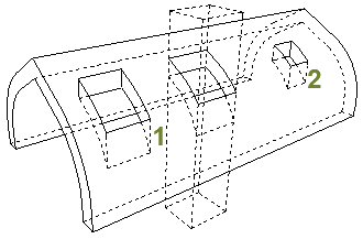
Number of holes in the Shell
Holes are either created in the Shell manually, or they are cut by Skylights placed in the Shell.

Number of Skylights
Number of Skylights placed into the Shell.

Openings Surface Area
Total surface area of all Skylights placed in the Shell.

Peaks Length
Length of edges whose Type is set to "Peak" in the Custom Edge Settings dialog box.
Typically, the edge at the top end of a single-plane Shell.
Revolution Angle
For a Revolved Shell only. Angle by which the Shell is rotated around its axis. Revolution angle value is set graphically, when creating the Shell, or in the Revolution Properties panel of Shell Settings or in the Info box.

Ridges Length
Length of edges whose Type is set to "Ridge" in the Custom Edge Settings dialog box.
Typically, the edge of two adjacent Shell planes that meet to form a ridge.
Side Wall Connection Length
Total length of all edges whose Type is set to "Side Wall" in the Custom Edge Settings dialog box.
Typically, a Shell edge which joins a Wall and runs along the Wall horizontally.

Start Angle
For an extruded Shell only. Angle of the Shell profile, measured to the Shell's inclination angle, at the starting end of the extruded Shell. Start angle value is set in the Extrusion Properties panel of Shell Settings or in the Info box.

Surface of the Shell on the Opposite to Reference Side
Name of the Surface assigned to the side opposite the Reference side.
Assign surfaces in the Model panel of Shell Settings

Surface of the Shell on the Reference Side
Name of the Surface assigned to the Reference side.
Reference side: The Shell membrane (the "top" of the Shell.) For a Composite Shell: The first listed skin of the composite structure, in Composite Settings.
Assign surfaces in the Model panel of Shell Settings

Trimming Body
Downward Extrusion, Upward Extrusion, or Editable.
Set in the Model Panel of Shell Settings.
Determines the geometry of the Trimming Body which acts upon other elements when they are trimmed by this Shell.
