Miscellaneous Settings - Export
Go to File > Interoperability > SAF > SAF Translators.
Use the Miscellaneous Settings - Export panel for the following options:
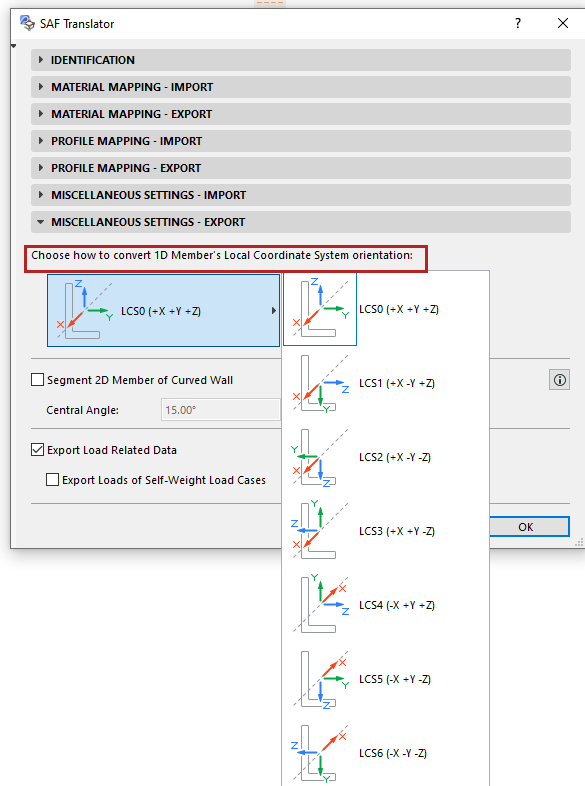
Local Coordinate System (Export to SAF)
In each receiving software, a cross section from the catalog is placed into the workspace based on its default XYZ orientation, as defined in the Local Coordinate System (LCS) of the host 1D Member.
Since the LCS standard varies by software, you must choose the standard which the receiving software uses: click one of the LCS standards shown in this panel of the SAF Export Translator.
At SAF file export, Archicad will convert the outgoing elements accordingly, so that 1D Member Cross Sections will be oriented correctly in the receiving software.

How Do I Know Which Local Coordinate System to Choose?
If you have imported predefined SAF Translator Settings optimized for a particular software, the Local Coordinate System is correctly defined.
See Download SAF Data Files optimized for structural applications.
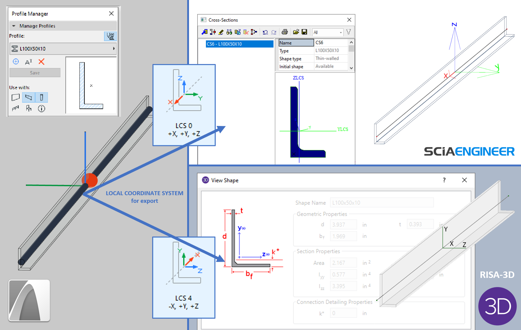
To identify the LCS used by the receiving software, do the following (and view the image below):
1.Map an L-shaped Archicad Profile Attribute to its counterpart in the receiving program. (Use a non-symmetrical profile - such as L - whose orientation is obvious.)
2.In the receiving software, place the corresponding L Cross Section using its default placement (without extra rotation or mirroring), so that it “faces” the same way as the Archicad profile.
3.View the placed Cross Section position in the LCS of the 1D member. Typically, European software (e.g. SCIA Engineer) use LCS 0, while U.S. software use LCS 4 (e.g. RISA-3D) or LCS 3.
4.In the SAF Translator for Export, choose the LCS option that corresponds to your receiving software.

Note: You do not have to set an LCS in the SAF Import translator. When importing a SAF file, Archicad automatically converts the incoming element positions, based on the “LCS of cross-section” Model data.
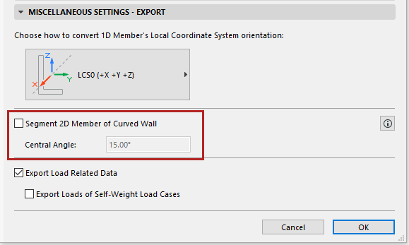
Segment 2D Member of Curved Wall
This control affects the SAF export of 2D Members that are generated from curved Walls.
Segmentation is off by default. Leave it off if your receiving structural analysis software can handle curved 2D Members generated from curved Walls.

When Should You Enable Segmentation?
Check the box only if your receiving structural analysis software cannot handle curved Walls. The curved 2D Member will be exported as multiple segments.
In the Central Angle field: Define a maximum central angle for the resulting segments.
–The resulting segments will approximate the central angle you have defined (without exceeding it), but are subject to the following adjustments:
-If the curved Wall contains additional nodes besides its endpoints (e.g. structural nodes where a connecting element meets the Wall), then segments will be created so that their endpoints coincide with these existing nodes.
-Based on these node locations, actual Central angle values (and segment lengths) will vary.
Important Notes
–If you enable Segment 2D Member of Curved Wall: the receiving software will generate additional segment endpoints to coincide with the nodes of any Structural Support and Structural Analytical Links that are attached to the curved Wall.
–The newly generated, inner edges of the exported Wall segments will have Edge releases set to Rigid (regardless of the Release values of the original Wall edges).
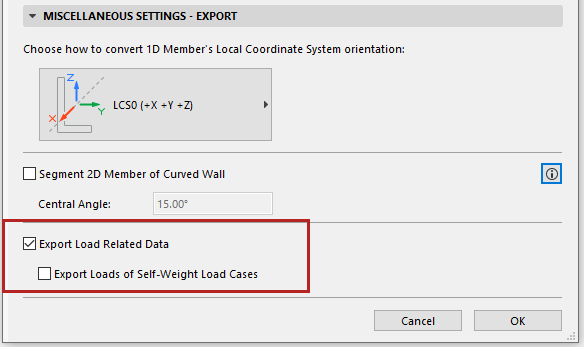
Export Load-Related Data
On by default.

Disable this control if you want to ignore all Load-related data when exporting the Structural Analytical Model to SAF.
For example, in the following scenarios involving data roundtrips:
•the structural software uses Load data not recognized by Archicad
•the architect chooses not to incorporate the SAF file’s Load data into the Archicad model
In such cases, roundtrip data exchange can result in the loss of Load-related data. To avoid this loss, you may wish to disable the checkbox. Load data will be ignored.
Export Loads of Self-Weight Load Cases
Off by default.
Most analytical programs do not handle self-weight Loads from external programs.