Linear Dimension Tool Settings
Dimension Type: Define how you want to calculate your linear dimension.

•With the Linear method, distances between two adjacent Reference Points are measured and displayed.


•With the Cumulative method, the first Reference Point is considered the zero point of the dimension chain. All dimension values of the chain will give you the distance between any Reference Point and the zero point.


•With the Base-line method, measuring the dimensioning distances is the same as with the Cumulative method, but the zero point is not marked.

•With the fourth icon, you create Elevation Dimensions.

See specific settings at Elevation Dimension Settings.
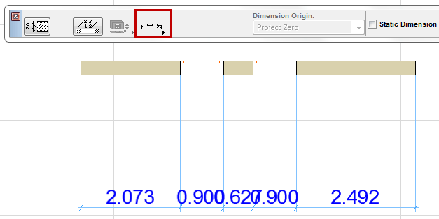
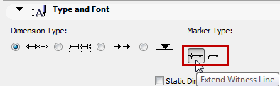
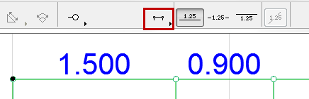
Extend Witness Line: Choose whether the witness line should extend past the node.

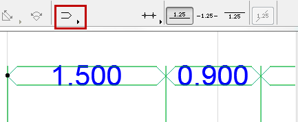
Click the Arrowhead pop-up to choose an arrowhead type for the Marker.
•The last arrowhead type results in a double Dimension Line enclosing the values. With this marker, value position settings are not effective.
Enable the Static Dimension checkbox to create static dimensions that are not associated with any of the elements in the Project.
Witness Line: Click one of the radio buttons to define the Witness Line format.

•Dimension without Witness Lines

•Dimension with Witness Lines sized to the Marker size.

Note: Marker Size is set below, at: Dimension Marker and Witness Line Options Panel.
•Dimension with Custom Witness Lines.

Note: Length of Custom Witness lines is set below, at: Dimension Marker and Witness Line Options Panel.
•Dimension with Dynamic Witness Lines (associated to the dimensioned element).

Note: The gap between the Witness Line and the dimensioned element is set below, at: Dimension Marker and Witness Line Options Panel.
Arrowhead for Pencolor/Penweight: Type a Pencolor/Penweight number (1-255) here for the Arrowhead marker.
Hint: For thicker Dimension Arrowheads, use a Pencolor with a heavier Penweight (defined in Options/Pens & Colors).
Dimension Line Pencolor/Penweight: Type a Pencolor/Penweight number (1-255) here for the Dimension Line.
Font Type: Click this pop-up field to select a font for the Dimension Text.
To the right, select a Pencolor and Pen weight for the Dimension Text.
Font Size: Enter a font size for the Dimension Text here. Note: Fractional sizes are allowed, but may be rounded.
Text Format: If desired, check the Bold, Italic, or Underline boxes to format the dimension text accordingly.
•Click here to place the Dimension Text above the Dimension Line.

•Click here to interrupt the dimension line with the dimension text.

•Click here to place the Dimension Text below the Dimension Line.

Horizontal Text: Check this box to display dimension text horizontally. (This is the default setting when the 3D Document window is active.)
For dimensions whose text is set to “Horizontal”, the text will remain horizontal with respect to the screen regardless of any rotation of the view.
See Oriented View.
Opaque: Check this box to set a background color for your dimension text block and activate the pencolor selection settings at right: open the pop-up menu to choose a color. The pen of this Fill may also be set to 0 (Transparent) or -1 (Window Background). Henceforth your text editor will also have this background color.
Frame: Check this box if you want the dimension text block frame to be visible. Checking the box activates the pencolor selection settings at right: open the pop-up palette to choose a color for the frame.
For more information, see Place a Linear Dimension.
Dimension Marker and Witness Line Options Panel
These options set the Witness Line options, depending on the type of Witness Line you chose in the Type and Font panel, above. (See Dimension Type and Font Panel.)
Marker Size: Enter the size of the marker here.
Dynamic Witness Line Gap: Enter the element-Witness Line gap value here for the Dynamic Witness Line.
Custom Witness Line Length: Enter the length of the Custom Witness Line here.
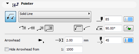
Use these settings for the optional pointer line(s) of the Dimension chain.
Click the Pointer button (available for a selected Dimension, but not in Default Settings) to assign a pointer line and activate the rest of the settings on this panel.
Note: Even if you have not turned on a Pointer Line for a Dimension text, a Pointer Line will automatically appear if you drag the Dimension text box beyond a certain range.
See Automatically Appearing Pointer Line (Dimension Text Only).
Define a Line type and Pencolor for the pointer line.
Choose whether the pointer should have a straight or a curved pointer line.
Enter the Pointer Starting Angle using a value from 0 to 90 (the default is 90 degrees). The angle is measured from the dimension line. Click the lock icon to prevent the angle from being modified graphically (e.g. by accident).
Note: The Lock Angle control affects the range of graphical editing. If it is ON, the Pointer Line’s starting angle remains fixed, limiting the edit possibilities.
Choose where the pointer line should connect with the label: in the middle, at the top or at the bottom; or at the bottom with the text underlined.
Choose a style and pencolor, and enter the size of the Arrowhead.
Hide Arrowhead from: Check this box if you want to hide the pointer line arrowheads on views which exceed a certain scale (enter the desired scale in the field to the right).
See also Graphical Editing of Text Box and Pointer Line.
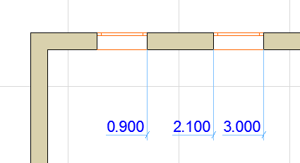
The Dimension Details panel contains options for the dimensioning of Windows and Doors and composite Walls.
Note: These controls are in addition to the options available through the Dimension Marker panel of the Door/Window Settings dialog boxes, and works for both smaller and larger sizes for German type reveals.
Display the Height of Openings as well: Check this box if you want the dimension marker to display the opening’s height value along with the width. If you check this box, choose one of the three radio buttons at right to define how to display the Height value:
•Always with Oversize: Include the opening’s vertical oversize, if any, in the Height value.
•Always without Oversize: Do not include any oversize when calculating the displayed Height value.
•Determined by Width: If the dimensioned Width includes an oversize, show Height with its Oversize. If the dimensioned Width does not include an oversize, do not include any oversize in the displayed Height value.
Dimension only the Core of Walls and Slabs: Check this box to dimension core thickness only for Walls and Slabs. Core dimensions are associative.
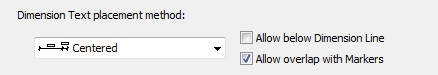
Dimension Text placement method:
Use these options to control how Dimension Texts should be adjusted if they become too crowded.
Note: These options are available if the dimension type is set to “linear” (not cumulative, baseline, or elevation). (See Dimension Type and Font Panel.)
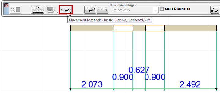
•Classic: The algorithm used in older versions of ARCHICAD.
•Dimension Texts are placed horizontally and in the middle of the measured segment.
•If there is not enough room, Dimension Texts are shifted sideways so as to be readable. Adjacent Dimension texts also shift sideways.
•If there’s no space to move sideways, they are adjusted vertically upwards, by rows.
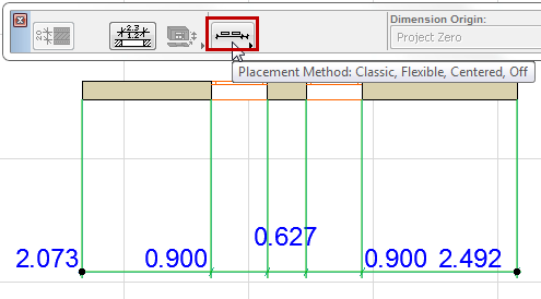
•Flexible (default): This method is more sophisticated than the Classic: it makes automatic adjustments even if a dimension text has been manually moved, or consists of multiple lines.
•Dimension Texts are placed horizontally and in the middle of the measured segment.
•If the space is too narrow, Dimension Texts will shift sideways. (Adjacent texts stay put.)
•If there is not enough space for a sideways shift, texts may be adjusted vertically.

Two additional checkmarks options are available with this method:
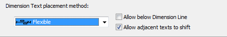
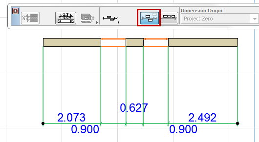
•Allow below dimension line: As part of the adjustment, texts may be displayed below the dimension line as well as above.
•Allow adjacent texts to shift: When a dimension text is shifted sideways, its adjacent dimension texts may also shift sideways (to the middle of the space remaining) as needed.
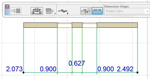
•All dimension texts are placed right in the middle of the measured segment. Nothing is adjusted sideways.
•If there is not enough room, they are adjusted vertically.
•Allow below dimension line: As part of the adjustment, texts may be displayed below the dimension line as well as above.
•Allow overlap with Markers: Texts may overlap with the dimension markers. (If this is off, then texts will be adjusted vertically to avoid overlap with Markers.)
•Off: No automatic adjustment takes place to enhance readability.
All the texts are simply placed in a row, directly above the dimension line without regard to readability.