Note: In Teamwork, the following data in the IFC Manager can be reserved and modified: IfcProject, IfcBuilding, IfcSite, Assignments and Type Products. IFC Properties of model elements (e.g. IfcWall, IfcColumn, IfcBeam) can be modified via IFC Manager only if those elements are not reserved by any other user.
Scheme Data
Attributes, Properties and Classification Reference entities defined by a scheme (IFC Scheme Setup) can have values that are optionally assigned or else derived.
To assign an optional scheme-defined Attribute or Property to an element, check the box in front of the element. Use the Value field to define its value depending on the value Type (e.g. Label, Integer, Boolean). To define values of a scheme-defined Classification Reference data, type them manually or use the Apply Predefined Rule command (see its function later, at Custom Data). Any element that is not assigned a value will be exported that way.
Derived values (identified with a lock icon) will come from a source of existing ArchiCAD data. If a derived value is shown in:
•black, it can be overwritten with a custom value
•grey, it cannot be modified here in the IFC Manager; it can be modified only at its source, where that particular ArchiCAD value comes from.
Examples for factory default mapping rules for IfcBeams:
•The Name Attribute is derived from the ArchiCAD Beam-classified element’s ID parameter (found in the Tags and Categories panel of Element Settings).
•The value of the IsExternal property (Pset_BeamCommon), either “True” or “False”, is derived from the corresponding ArchiCAD element’s Position classification (either “Exterior” or “Interior”).
•The value of the LoadBearing property (Pset_BeamCommon), either “True” or “False”, is derived from the corresponding ArchiCAD element’s Structural Function classification (either “Load-Bearing Element” or “Non-Load-Bearing Element”).
Derived Properties can also originate from the mapping rules used in IFC Scheme Setup.
See IFC Scheme Setup.
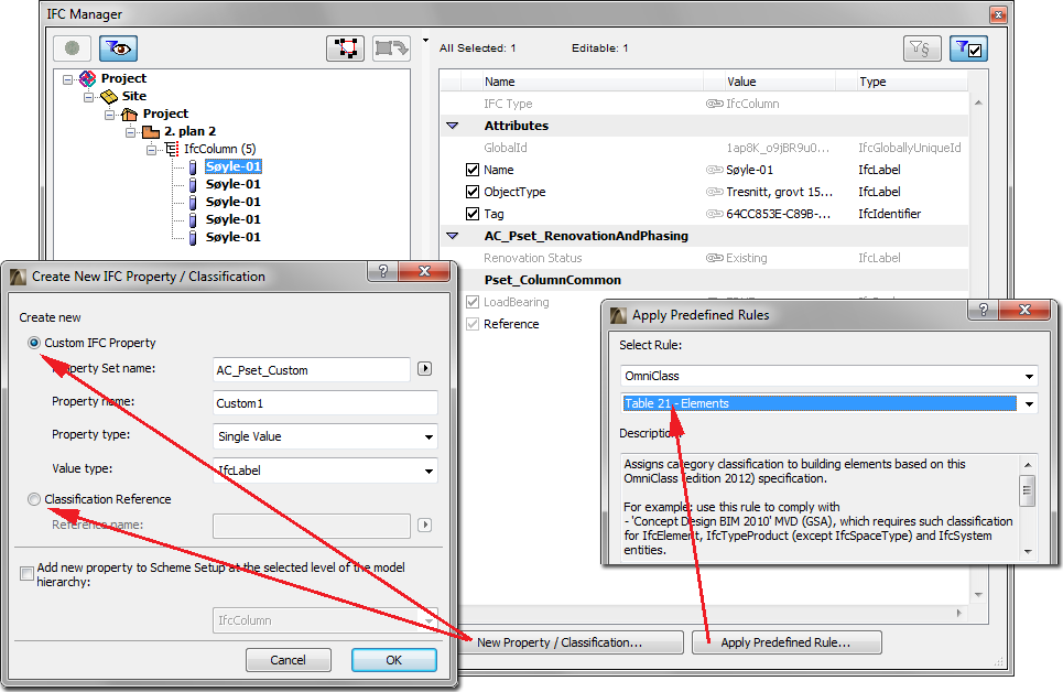
Use the New Property/Classification option to create new custom IFC Properties or Classification References. Alternatively, use the Apply Predefined Rule command to create them automatically.
To create a new custom IFC Property:
1.Define a name for the new custom Property Set; or else choose from the list of existing Property Set names defined previously for the same element type (click the arrow icon to access this list). For example, if you are creating a new Property for an IfcWall, the list contains all the Pset names earlier assigned to other IfcWalls.
Note: To avoid errors (and to keep the standard property definition rules), do not use the standard “Pset” prefix when giving a name to your custom Property Sets.
2.Define a name for the new custom Property.
3.Set the type of the new Property (single, enumerated, complex, etc.).
4.According to the Property type, set its value type to label, text, integer, boolean, etc.
To create a new Classification Reference, just assign it a name. Here, too, you can choose from the list of existing Classification Reference names defined previously for the same element type (click the arrow icon to access this list).
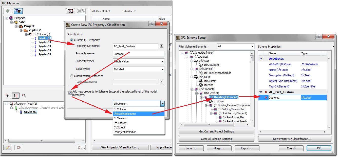
Having defined a new Property (together with its Property Set container), you can apply it to other elements too, not just the one you are editing. For example, if you have created the new data for a selected IfcWall element, you can add the new data to all elements of the same type as the selected one (all IfcWall entities), or to other elements of the current project/IFC model. Use “Add new property to Scheme Setup...” and set the level of the model hierarchy that contains the requested IFC Entity type(s) you would like to add the new property. For example, in the previous IfcWall case, choose
•“IfcBuildingElement”, if you would like to define the new property for all IfcColumns, IfcBeams, IfcSlab etc. besides of all IfcWalls;
•“IfcElement” to add the property to all HVAC elements (IfcDistributionElements) too,
•“IfcProduct” to also add the property to all spatial elements including IfcSpaces, IfcBuildingStorey, IfcBuilding and IfcSite;
•“IfcObject” to add the new property to all Assignments too;
•the highest level “IfcObjectDefinition” to add all project elements including all IFC Type Product types (not only the IfcWallType)
These options will also work for new elements to be created in the future (any new IfcWalls, or any new element, depending on the chosen option) will automatically be assigned this data. The Properties that are thus created are added to IFC Scheme Setup. To understand the model hierarchy’s levels and their containments (and the examples mentioned before), see the next figure or check the hierarchy tree in the dialog of IFC Scheme Setup.
See IFC Scheme Setup.
Newly created IFC data will appear in the defined Property Set or “Classification Reference” folder in the IFC Manager, as well as in the element Settings dialog among the listed properties. Assign values to the new data according to its value type. For example, a Classification Reference data has 7 available items (the most important ones are the name (Name) and the identifier (ItemReference) of the classification reference data) for defining/editing. Such newly created IFC data appears with a red X in front, meaning that you can delete them at any time. If a Property Set no longer contains any Properties, it will be deleted from the list automatically. To rename a Property Set, Property or Classification Reference, click on the name, then re-write it.
Custom IFC Properties (and Property Sets) may also be created through the IFC Scheme Setup command (these Settings will also contain the data created by using the above-mentioned “Add new property to Scheme Setup...” option). These data can only be edited (deleted, renamed) using the IFC Scheme Setup command.
To create a new Assignment, do the following in the IFC Manager:
1.Switch to Assignment view/definition mode by clicking the Assignments icon.
2.Select the Assignment type by clicking on the “IFC Groups”, “IFC Zones”, “IFC Systems”, “Actors”, “Space Occupants” or “Time Series Schedules” item.
3.Click the New button under the Assignments window section.
4.Select the new item, whose default name starts with “New”... and ends with the created Assignment type (e.g. New Group).
5.Give a (new) name to the new Assignment on the right side of the dialog in the Name Attribute field.
6.Edit the Attributes and/or the content of the available properties.
7.Add custom IFC data using the New Property/Classification option if needed (see above).
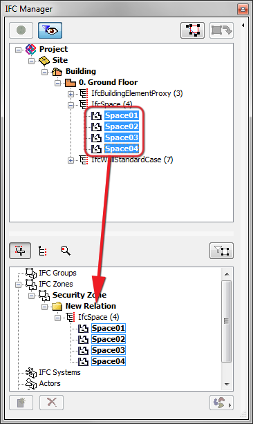
8.Drag and drop IFC Entities into the “New Relation” folder from the containment tree.
Notes:
•The Entity types that can be dragged into the new Assignment depend on the Assignment type. For example, you can only group IfcSpaces (ArchiCAD Zones) into an IFC Zone; while you can group both IfcSpaces and already existing IFC Zones within a Space Occupant (IfcOccupant). The latter case demonstrates that the member of an Assignment can itself serve as an Assignment.
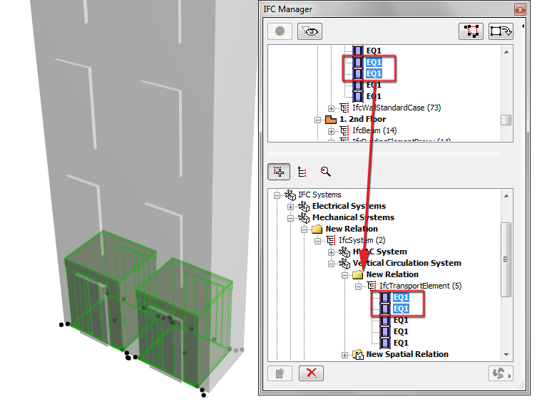
•In case of IFC System, spatial relation can also be assigned to the elements grouped in “New Relation”. Just drag and drop the required spatial element(s), such as ArchiCAD Zones (IfcSpace), Stories (IfcBuildingElementStorey), IFC Building and/or IFC Site, into the “New Spatial Relation” folder.
•If your project uses the MEP Modeler Add-On, then its defined MEP Systems can do the following:
•They can be classified as IFC Systems. Create a new, empty IFC System. Select it, then click on the MEP icon at the right (underneath the Assignment list), and choose the desired MEP System from the drop-down menu. All elements of the selected MEP System will automatically be added from the containment tree into the “New Relation” folder; the system’s name (Name Attribute) will be the same as the chosen MEP System.
•They can be added to an existing IFC System. Select an existing IFC System in the list, then choose an MEP System as described above. The existing IFC System is renamed according to the chosen MEP System, and all elements of that MEP System are added to the existing contents of the IFC System. In both cases, the system icon changes to the MEP “propeller” icon, indicating that an MEP System is being used. To delete MEP System elements from an IFC System, select the system item (which is now named after the MEP System whose elements you want to delete), and choose “Disconnected” from the drop-down menu of the MEP System options.
•Multilevel (“Sub”) hierarchy is available for IFC Group, IFC Zone and IFC System assignments. Sub-hierarchy (for example child systems in a parent system) can be defined easily:
•drag and drop a predefined assignment into an existing “New Relation” (or named relation) folder of the same type target assignment, or click New, with the “New Relation” (or named relation) folder of the “parent” assignment selected, to define a new “child” assignment
•a parent assignment moved into a different parent assignment becomes a “child” of that assignment (this is a move)
•a child assignment can be either moved or copied into a different parent assignment (to copy it, hold down Ctrl/Alt while dragging it)
•to make a child assignment into a parent assignment, select it and drag it outside of the dialog box; it will reappear in the hierarchy as a parent assignment
•If needed, define a name for the New Relation on the right side of the dialog in the Name Attribute field.
•Use the Delete (red X) button to delete a Relation or Assignment.
See IFC Assignments.
Examples:
•Create an IfcZone named “Security Zone”, which will group together all of the project’s IfcSpaces that have a security function.
•Group elevators in a vertical circulation system, which can be a child system of a mechanical system.
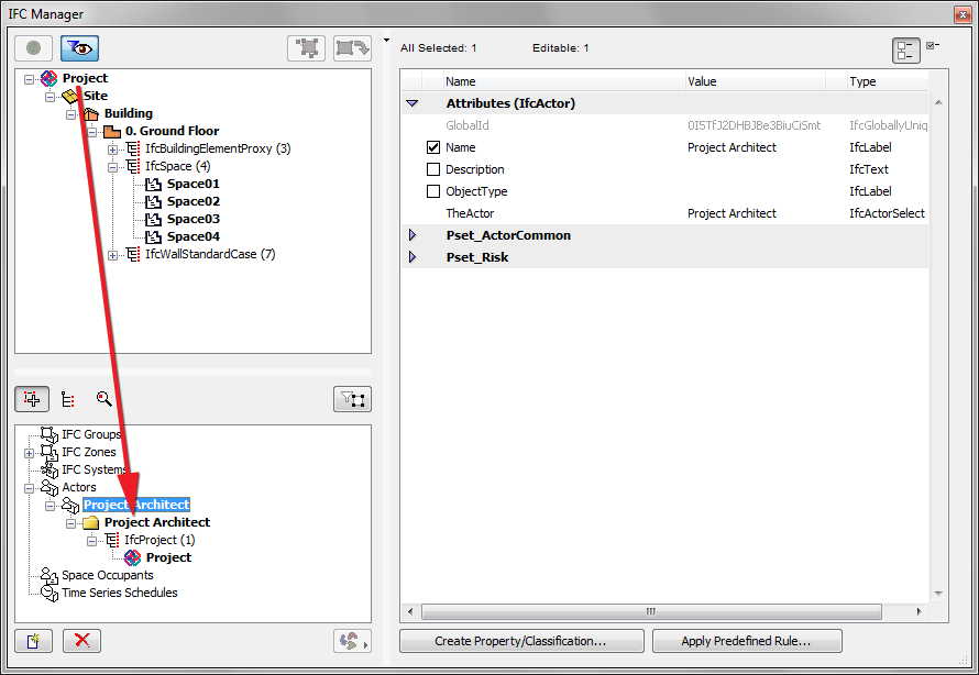
•Define the Project Architect as an Actor, whose only element is the IfcProject, with an Actor Attribute of “Person”.
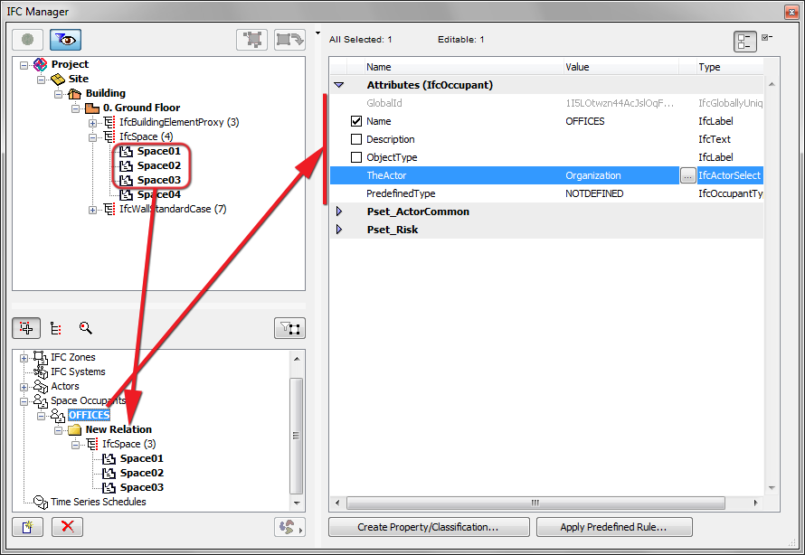
•Using a new Space Occupant, group together all the IfcSpaces whose owner is an Organization.
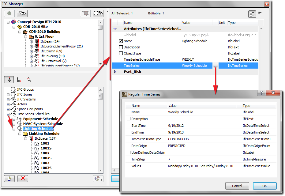
•Using a new Time Series Schedule, define an assignment of a weekly schedule (of the times when lighting is turned on and off) to IfcSpaces.
The IFC Manager locates and displays all the IFC Type Products that exist in the project, plus all the elements which refer to them. To see them, switch to the Type Products view/definition mode using the second icon underneath the containment tree. In the appearing list, select the type (e.g. IfcWallType) or style (e.g. IfcWindowStyle) or its related elements, to check and edit their IFC Data on the right side of the IFC Manager.
As soon as it is placed, an ArchiCAD element is automatically assigned an IFC Type Product that corresponds to its IFC entity type (or Element Classification). For example, if an ArchiCAD Slab has an Element Classification of “ArchiCAD Type” (IfcSlab), then its IFC Type Product will be IfcSlabType. If its Classification is “Ceiling” (IfcCovering) then its type will be IfcCoveringType. The default name of the type is generated automatically, as described in the IFC Type Product section of this documentation. Based on this naming convention, several ArchiCAD/IFC elements will be assigned to a particular IFC Type Product. For example, ArchiCAD columns (IfcColumns) having identically named profiles will be assigned to a single type that is named after that profile.
See IFC Type Product.
The data (e.g. name) of the resulting IFC Type Product are not editable by default; they are displayed in italicized grey type, and all IFC data on the right side are greyed. In this case, no new IFC data (e.g. custom IFC Property or Classification Reference) can be assigned to the type either.
You may wish to edit an IFC Type Product. For example:
•change its name (which is the Name IFC Attribute)
•define a value for an Attribute or standard Property that has no value yet
•modify existing Property data
•create a new custom Property or Classification Reference data
See Creating and Editing IFC Data.
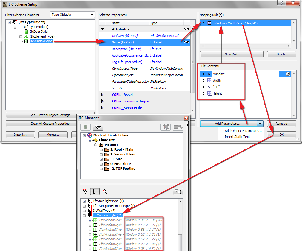
You can apply ArchiCAD data mapping rules to the IFC data of IFC Type Product elements. For example, generate the names of Window types (Name Attribute of IfcWindowStyle) from the combination of the Library Part Name, the Width and Height parameters of Window.
See IFC Scheme Setup.
To edit the IFC Type Product, first enable it for editing: click on the “Edit/New Type” button. Then make the desired modifications. To revert the data of the IFC Type Product to their default values, click the “Reset Type” button.
Note: “Reset Type” means that all edited IFC data will revert to their original values, and the new data will be deleted.
It is possible to combine several IFC Type Products entities (provided they are editable, that is, activated using the “Edit/New Type” button) into a single IFC Type Product - for example, combine two IfcWindowStyle types into a single IfcWindowStyle. This combination can take the following forms:
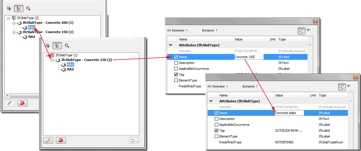
•Apply an existing IFC Type Product to other types. This works for all element types except Doors/Windows (see below for explanation). For example, suppose you have two concrete Slabs of different thicknesses. By default, these will be classified as two separate IFC Type Products (IfcSlabType), because thickness is a significant property of slabs. But you want to combine them into a new, single type named “Concrete slabs.” Defining them is easy: select one of the IfcSlabs from its type folder and drag in into the other slab type (drag it onto the slab type name). This way, it will be deleted from its original location and placed into the other type. Next, change the name of the second type (which now contains two elements) to “Concrete slabs” (see illustration below).
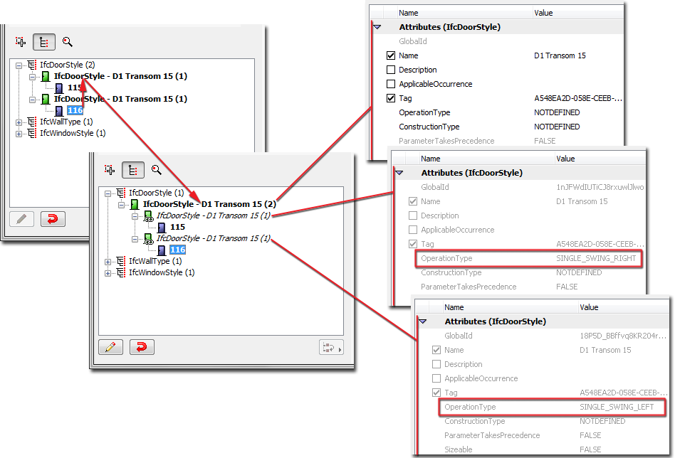
•Combining doors or windows is more complicated, because some of their major parameters are generated from GDL data, and cannot be modified as a result of combining elements. Such parameters are the OperationTypeAttribute and the Panel and Lining attributes. Suppose you have two doors that are identical in all their data (e.g. size, panel type), but their Operation Types are different: one opens to the right, the other to the left. These two doors will be classified under two different IFC Type Products: these two Types will have the same name, but their “OperationType” IFC Attributes will differ. To have both doors belong to the same IFC Type Product, select one of the doors and place it in the other (second) type. As a result, a new, common type is created that uses all of the non-generated data of the second type (such as Name Attribute, Properties, Classification Reference, etc.). This new common type is the one that will be exported, and which will be assigned to both of the doors. This common type can be renamed and its data modified. At the same time, the two original types will remain as so-called linked types, and will link to the elements only data which is generated and which differ for each of the two doors (in this case, their OperationType Attributes). In other words, both doors will belong to a single type, which includes all of the data they have in common, but they will also maintain certain IFC data that were different for each and cannot be combined (see illustration below).
The “Reset Type” option can do the following:
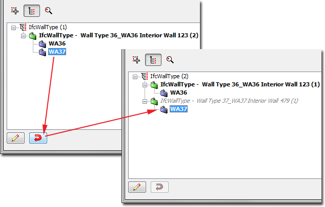
•When applied to a selected IFC Type Product (e.g. IfcWallType) that has been edited, the Type’s original data are restored (newly modified IFC data are lost), and the Type is no longer editable. If the Type now contains new elements as a result of combining Types, then those elements will return to their original locations.
•When applied to a single element (e.g. IfcWall) that has been moved into a different Type, that element will return to its original location where it was automatically assigned by the program.
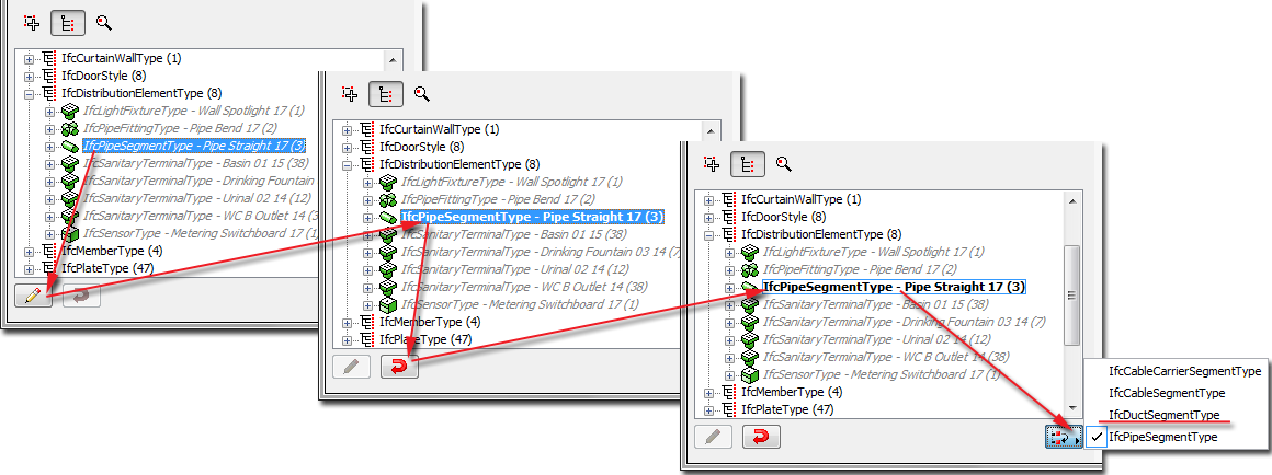
For some ArchiCAD elements, automatic definition as a particular IFC Type Product is not always clear-cut - typically the case for HVAC elements (IfcDistributionElements). Suppose you have an MEP Modeler Pipe element. By default, its IFC Entity classification is IfcFlowSegment. But its IFC Type Product definition can be even more specific (see illustration below). The program will automatically choose a subtype of the IfcFlowSegmentType (e.g. IfcPipeSegmentType). You can modify this later to be a different subtype of the IfcFlowSegmentType (such as IfcDuctSegmentType): use the “Change Type Product” drop-down menu. (Make sure you have made the IFC Type Product editable, using the “Edit/New Type” function described above.)
You can assign new IFC data to selected elements based on automatic (.xml-based) rules, using the Apply Predefined Rule button. There are three types of such rules, based on their differing structures:
•“Tree list” rule: select an element from a tree-structure database to create the new data
•“Table” rule: select a row from a table to create the new data
•“Command” rule: Start the rule-command to create the new data
The program contains factory-defined built-in rules (these vary depending on your localized version of ArchiCAD). As an example, the following table summarizes the rules that are contained in every language version of ArchiCAD:
|
Rule name |
Related object |
Rule type |
Function |
New IFC data |
Rule file |
|
OmniClass / Table 11 - Construction Entities by Function |
IfcSite, IfcBuilding and IfcBuildingStorey |
Tree list |
Assigns a functional classification to IFC Building, IFC Site and ArchiCAD Stories based on this OmniClass specification |
Classification Reference |
OmniClass.xml |
|
OmniClass / Table 13 - Space by Function |
IfcSpace and IfcSpaceType |
Tree list |
Assigns a functional classification to ArchiCAD Zones based on this OmniClass specification |
Classification Reference |
OmniClass.xml |
|
OmniClass / Table 21 - Elements |
IfcElement, IfcBuildingElementType, IfcDistributionElementType, IfcElementComponentType, IfcFurnishingEleemntType, IfcTransportElementType, IfcDoorStyle, IfcWindowStyle and IfcGroup |
Tree list |
Assigns category classification to building elements based on this OmniClass specification |
Classification Reference |
OmniClass.xml |
|
OmniClass / Table 23 - Products |
IfcElement, IfcBuildingElementType, IfcDistributionElementType, IfcElementComponentType, IfcFurnishingEleemntType, IfcTransportElementType, IfcDoorStyle, IfcWindowStyle and IfcGroup |
Tree list |
Assigns construction product classes to building elements based on this OmniClass specification |
Classification Reference |
OmniClass.xml |
|
Concept Design BIM 2010 (US GSA) / Project Client/Owner and Project Architect |
IfcProject |
Command |
Defines the GSA-required Actor-system items for the current project |
Actor |
Concept Design BIM 2010 (US GSA).xml |
|
Concept Design BIM 2010 (US GSA) / Space Type (Owner) |
IfcSpace and IfcSpaceType |
Table |
Assigns a type classification to ArchiCAD Zones based on GSA's STAR Space Type specification |
Classification Reference |
Concept Design BIM 2010 (US GSA).xml |
|
Concept Design BIM 2010 (US GSA) / Space Category (Owner) |
IfcSpace and IfcSpaceType |
Table |
Assigns a category classification to ArchiCAD Zones based on GSA's STAR Space Category specification |
Classification Reference |
Concept Design BIM 2010 (US GSA).xml |
|
Concept Design BIM 2010 (US GSA) / Space Category (BOMA) |
IfcSpace and IfcSpaceType |
Table |
Assigns a category classification to ArchiCAD Zones based on the requirements defined by the American National Standard Institute (ANSI) and the Building Owners Management Association (BOMA) |
Classification Reference |
Concept Design BIM 2010 (US GSA).xml |
|
Concept Design BIM 2010 (US GSA) / Spatial Zone Type (Energy Analysis) |
IfcZone |
Table |
Assigns a type classification to IFC Zones based on the requirements defined by ASHRAE 90.1 Common Space Type |
Classification Reference |
Concept Design BIM 2010 (US GSA).xml |
|
Concept Design BIM 2010 (US GSA) / Space Occupant Classification and Properties |
IfcOccupant |
Table |
Classifies organizations that occupy ArchiCAD Zones, Stories and IFC Building based on CDB-2010’s ‘Occupant Properties Lookup Table’ |
Classification Reference, custom IFC Property |
Concept Design BIM 2010 (US GSA).xml |
|
Uniclass tables… |
IfcElement, IfcSpace, IfcZone, IfcElementType etc. depending on the chosen table of Uniclass standard |
Tree list |
Assigns a functional or category classification to building or spatial elements based on different Uniclass tables |
Classification Reference |
Uniclass.xml |
Examples:
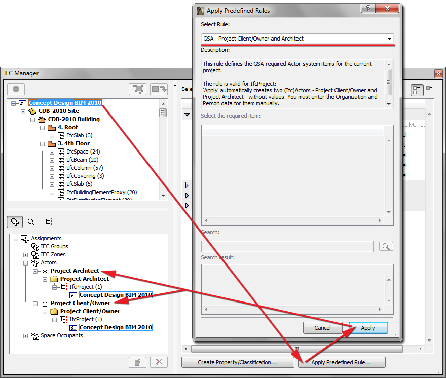
•Apply the “Concept Design BIM 2010 (US GSA) / Project Client/Owner and Project Architect” rule on the IfcProject entity (the highest level of the IFC Model hierarch) selected in the containment tree of the IFC Manager. As a result, Actors (IfcActor) are created with the following relations: “Project Client/Owner” and “Project Architect.”
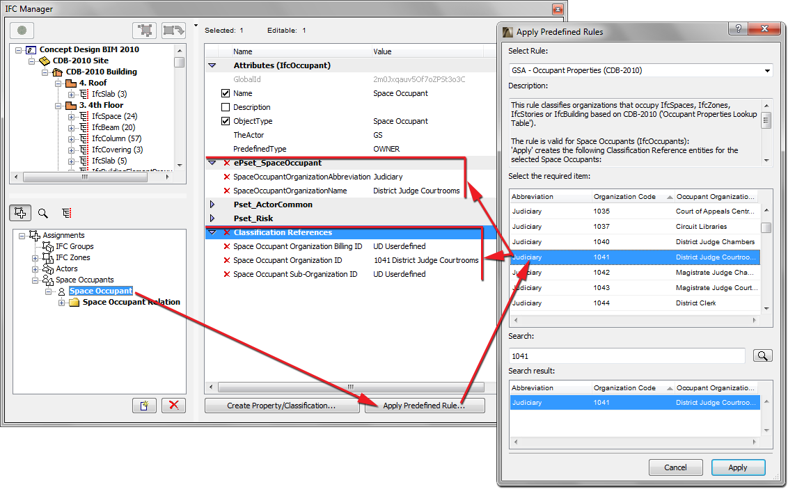
•Assign a Space Occupant classification by using the “Concept Design BIM 2010 (US GSA) / Space Occupant Classification and Properties” rule:
1.Create the new Space Occupant, then drag in the elements that belong to it (e.g. IfcSpace entities).
See IFC Assignments.
2.Select the Space Occupant name in the Assignment list, then use the Apply Predefined Rule tool. From the dialog box, choose the “Concept Design BIM 2010 (US GSA) / Space Occupant Classification and Properties” rule.
3.From the table, select the desired classification item.
4.Click Apply. The Classification Reference elements and Properties are generated for the Space Occupant, using the values corresponding to the selected classification item.
You can search among the rules in the databases (tree list and table) by entering any partial text.
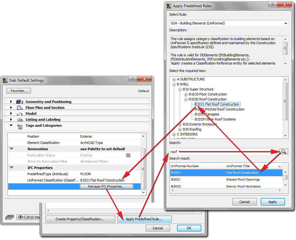
For example, let us assign classifications to a number of roof slabs (IfcSlabs) using the “OmniClass / Table 21 - Elements” rule:
1.In the model, select the Slab elements to be classified (you can use Find & Select). Open the Settings dialog box and click on Manage IFC Properties from the Tags and Categories Panel. Alternatively, select the corresponding IfcSlab entities from the IFC Manager containment tree.
2.Use the Apply Predefined Rule tool. From the dialog box, choose the “OmniClass / Table 21 - Elements” rule.
3.In the database search field, enter the text “roof”.
4.From the Search results area, select the “Roof Decks, Slabs, and Sheathing” title. As a result, the same item will be selected in the tree list.
5.Click Apply. The Classification Reference is generated, with the name of “Roof Decks, Slabs, and Sheathing”, with an ItemReference value of “21-02 10 20 20”, and additional data corresponding to the OmniClass standard.
Note:
•Once you select an element, only the applicable rules are available in the “Select Rule” list (for example, if you have selected IfcProject, then the “Concept Design BIM 2010 (US GSA) / Project Client/Owner and Project Architect” rule is available). All the non-applicable rules are grayed.
•IfcElement includes building, distribution (MEP) and furnishing elements.
•Certain rules are not available in Settings dialogs if the rules are related to elements (for example, IfcBuilding, IfcBuildingStorey, IfcOccupant, IfcProject and IfcGroup) which do not have Settings dialogs.
•You can create and edit your own rule in .xml format. It is recommended to peruse the structure of an existing rule file (which may contain multiple rules), and to create a similar new rule by duplicating it under a different name.
•The available rules are accessible from the following folder, and the newly created rules should also be saved to this location:
-On Windows:
\Users\user name\GRAPHISOFT\IFC Rules “ArchiCAD version”
-On MacOS:
/Users/user name/Library/Application Support/GRAPHISOFT/IFC Rules “ArchiCAD version”